


8 - 1 8 - 1
MELSEC-Q
8 TROUBLESHOOTING
8 TROUBLESHOOTING
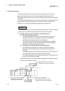
In order to ensure high system reliability, it is important to take precautions before the
system is operated and to quickly and effectively correct problems if they do occur.
This is why it is important to perform off-line testing of the network and checking of the
cables when first starting the system.
Make sure to perform the following checks, which are explained in Chapter 4, "Setup
and Procedures Before Starting the Operation."
1) Standalone operation check and operational setting of the network module
2) Offline tests:
Hardware test, Internal self-loopback test, self-loopback test and forward
loop/reverse loop test.
3) Check the connection of the data link cable.
Network diagnostic loop test (requires optical system)
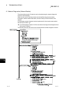
Even with this, if an error does occur, it is important to quickly and accurately
understand the nature of the problem. The following are three methods for confirming
the contents of an error.
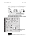
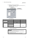
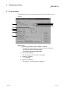
(1) Network diagnostics to remote master station with GX Developer
(a) Network monitor (refer to Section 8.1)
The status of the following four types of networks can be checked by
monitoring the line:
1) Status of the entire network: Host information
2) Data link status and parameter status, etc. of each station:
Other station information
3) Control station information, detailed data link information, etc.:
Network monitor details
4) Loop switch count, line error, communication error, etc.:
Error history monitor
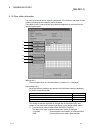
(b) Diagnostic tests (refer to Sections 4.10)
The following four items can be checked or executed through the diagnostic
tests:
1) Wiring status (IN/OUT, etc.) of the data link cable:
Loop test (required for optical loop system)
2) Setting status of numbers: whether the same station number has been set
for two or more stations, whether two or more control stations/remote
master stations exist, network numbers, and group numbers: Setup
confirmation test
3) The order of stations connected in the direction of the forward loop and
the reverse loop: Station order check test
4) Setting status of the routing parameters: Communication test
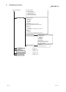
(2) Confirmation by error code: Refer to Section 8.3
When either cyclic transmission or transient transmission using link dedicated
instructions or GX Developer (communication with other stations) was not
normally performed, an error code is stored in the link special register and the
system monitor.
The contents of the error can be checked using this error code.
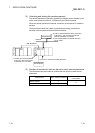
(3) Confirmation by the LEDs on the front of the network module
(Refer to Section 4.2)
With the LED displays, the following errors can be checked: whether the host is
operating or stopped, whether the station acts as a control station or a normal
station, whether the baton pass is being executed, whether data linking is being
executed, whether data are being transmitted/received, and whether any error
has occurred.
(4) Confirmation of the error history of the entire system (Refer to
Section 8.3)
By using GX Works2, the error history of the entire system can be checked even
after errors were cleared by turning on and off the programmable controller or by
resetting the programmable controller CPU.
8