


4 - 24 4 - 24
MELSEC-Q
4 SETTING AND PROCEDURE BEFORE OPERATION
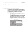
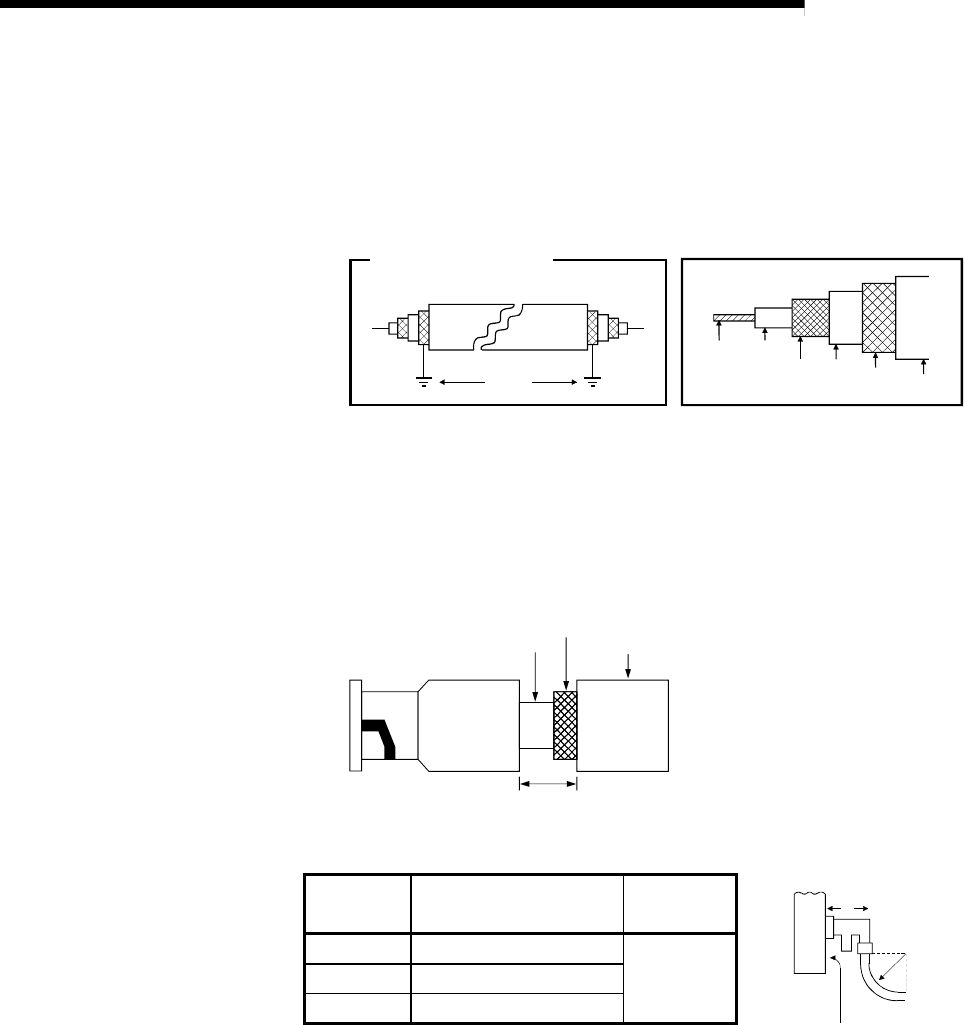
(b) Cable installation precautions
1) Install the coaxial cables at least 100 mm (3.94 in.) away from other
power cables and control cables.
2) Consider to use double shield coaxial cables in locations where there
is excessive noise.
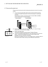
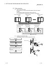
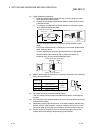
3) To configure a multiplexed remote I/O network for redundant system,
use a double shield coaxial cable.
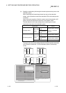
Ground
Mitsubishi Cable · · · 5C-2V-CCY
Double shield coaxial cable
Internal
conductor
Insulator
External
conductor
Sheath
Cable close-up
Sheath
External
conductor
(ground)
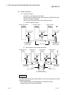
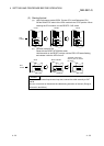
A 5C-2V connector plug can be applied to double-shielded coaxial
cable.
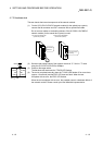
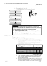
Ground the shielded section, external part of the double shield coaxial
cable, as shown above.
Connect the external conductor (grounding surface) of the double-
shielded coaxial cable 10mm (0.394 in.) away from the 5C-2V
connector plug. (Avoid connection between them.)
External conductor (Grounding)
Approx. 10 mm (0.394 in)
Sheath
Sheath
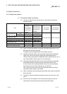
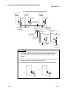
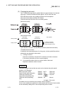
(c) When a coaxial cable is connected, the following restrictions on the bending
radius must be observed.
Cable type
Allowable bending radius
r
Connector
A
A
r
Front of module
3C – 2V 23mm (0.91 in.)
55mm
(2.17 in.)
5C – 2V 30mm (1.18 in.)
5C – FB 30mm (1.18 in.)
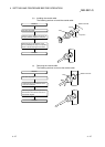
(d) Do not pull any of the connected coaxial cables.
This may cause a faulty contact and cable disconnection, or damage the
module.
(e) For coaxial bus type network systems, be sure to connect both end stations
to the terminal register.
(f) Depending on the usage environment, some white oxidation deposits may
be seen on the F type connector. However, oxidation will not occur on the
connection area, so there will be no problems with the function of the unit.
(g) Be sure to shut off all phases of the external power supply used in the
system before connecting or disconnecting coaxial cables.