


App - 32 App - 32
MELSEC-Q
APPENDICES
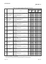
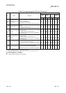
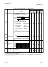
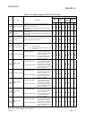
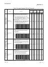
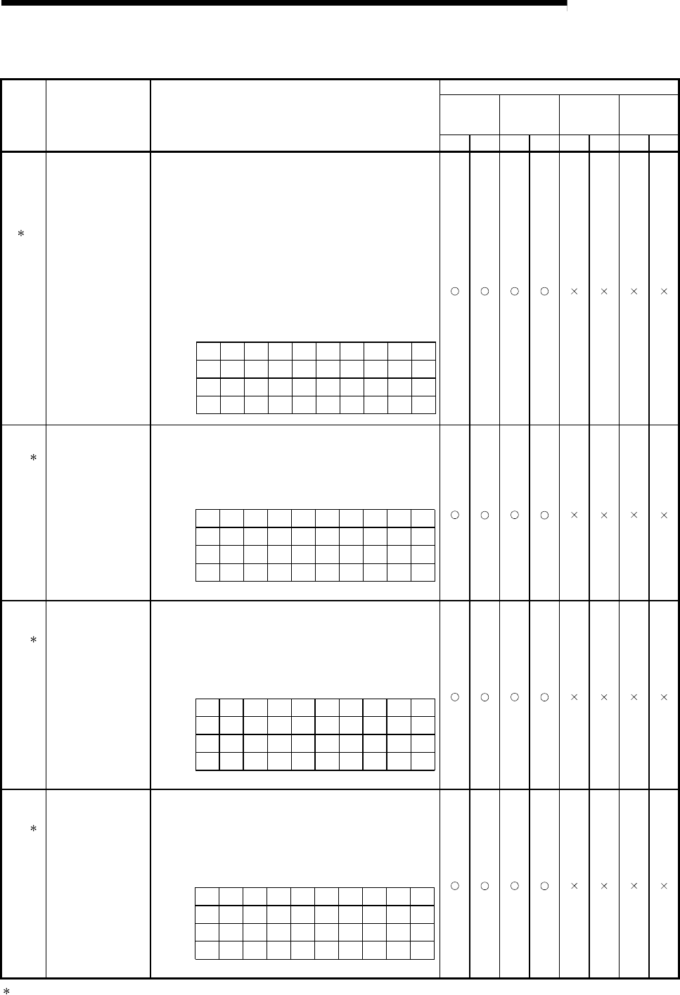
Table 3 Link special register (SW) list (Continued)
No. Name Description
Availability
Control
station
Normal
station
Remote
master
station
Remote I/O
station
Optical Coaxial Optical Coaxial Optical Coaxial Optical Coaxial
2
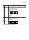
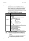
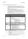
SW01E0
(480)/
SW01E1
(481)/
SW01E2
(482)/
SW01E3
(483)
Network type
consistency check
Indicates whether there is a mismatch between the network types
of the control station and normal stations on the network.
• When the control station is in the MELSECNET/H Extended
mode
0: Set to the MELSECNET/H Extended mode. (Including
stations of station Nos. greater than the maximum, reserved
stations and communication error stations)
1: Set to the MELSECNET/H mode or MELSECNET/10 mode.
• When the control station is in the MELSECNET/H mode or
MELSECNET/10 mode
0: Set to the MELSECNET/H mode or MELSECNET/10 mode.
(Including stations of station Nos. greater than the maximum,
reserved stations and communication error stations)
1: Set to the MELSECNET/H Extended mode.
16
32
48
64
15 14 13 5 4 3 2 1
31 30
47 46
63 62
29
45
61
21 20 19 18 17
37 36 35
34
33
53 52 51 50 49
to
to
to
to
b15 b14 b13 b12 b4 b3 b2 b1 b0
SW01E0
SW01E1
SW01E2
SW01E3
1 to 64 in the table indicate the station Nos.
to
2
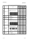
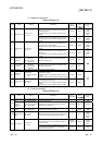
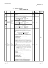
SW01F4
(500)/
SW01F5
(501)/
SW01F6
(502)/
SW01F7
(503)
Redundant system
status (1)
Indicates the operation mode of each station's CPU.
0: Backup mode (including the single CPU system) (including
stations exceeding the maximum station number and
reserved stations)
1: Separate mode
16
32
48
64
15
14
13 5
4
3
21
31 30
47 46
63 62
29
45
61
21 20 19 18 17
37 36 35
34
33
53 52 51 50 49
b15 b14 b13 b12 b4 b3 b2 b1 b0
SW01F4
SW01F5
SW01F6
SW01F7
to
to
to
to
to
Numbers 1 to 64 in the above table
indicate the station numbers.
2
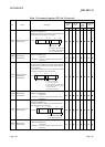
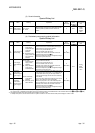
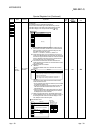
SW01F8
(504)/
SW01F9
(505)/
SW01FA
(506)/
SW01FB
(507)
Redundant system
status (2)
Indicates the pairing setting status of each station.
In the case of a redundant system, the bit of the station with the
larger number is turned on (1).
0: No pairing designation (including the single CPU system)
(including stations exceeding the maximum station number)
1: Station with pairing designation
16
32
48
64
15
14
13 5
4
3
21
31 30
47 46
63 62
29
45
61
21 20 19 18 17
37 36 35
34
33
53 52 51 50 49
b15 b14 b13 b12 b4 b3 b2 b1 b0
SW01F8
SW01F9
SW01FA
SW01FB
Numbers 1 to 64 in the above table
indicate the station numbers.
to
to
to
to
to
2
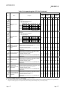
SW01FC
(508)/
SW01FD
(509)/
SW01FE
(510)/
SW01FF
(511)
Redundant system
status (3)
Indicates the operation status of each station's CPU (control
system/standby system).
0: The host station CPU is on the control system (including the
single CPU system) (including stations exceeding the
maximum station number and reserved stations).
1: The host system CPU is on the standby system.
16
32
48
64
15 14 13 5 4 3 2 1
31 30
47 46
63 62
29
45
61
21 20 19 18 17
37 36 35
34
33
53 52 51 50 49
b15 b14 b13 b12 b4 b3 b2 b1 b0
SW01FC
SW01FD
SW01FE
SW01FF
Numbers 1 to 64 in the above table
indicate the station numbers.
to
to
to
to
to
2: Valid only when SB0047 is off. When it turns on (error), the last data are retained.