


3 - 20 3 - 20
MELSEC-Q
3 SPECIFICATIONS
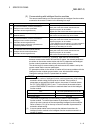
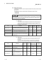
(c) Precautions in using the optical loop system
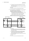
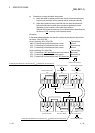
1) When the cable is inserted or removed, the line (forward loop/reverse
loop) may be switched, but the data link will be performed normally.
2) When the loopback is being executed due to a cable disconnection,
both the forward and reverse loops may be recognized as normal
depending on the condition of the cable disconnection.
Whether the forward/reverse loop is normal/abnormal is determined by
the status of "RD" (receive) of the loopback station.
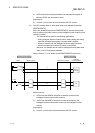
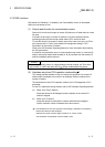
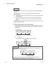
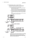
(Example)
In the cases described below, the data link continue by dividing the network into
two loops: "1M
R-1R5-1R6"
<Loop containing 1M
R
1-1R4-1R5>
1M
R
1: Forward loop normal/reverse loop normal
1R4 : Forward loop normal/reverse loop normal
1R5 : Forward loop normal/reverse loop normal
<Loop containing 1R1-1R2-1R3>
1R1 : Forward loop "RD" abnormal/reverse loop normal
1R2 : Forward loop normal/reverse loop normal
1R3 : Forward loop normal/reverse loop "RD" abnormal
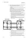
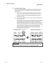
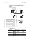
Forward loop
abnormal
Reverse loop
abnormal
Forward loop
normal
Reverse loop
normal
Communication disabled
Loopback
1M
R
Loopback
1R1 1R2
1R5 1R4 1R3
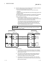
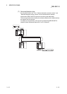
Remote master station
Forward
RD
An RD abnormal detection in the forward loop Loopback with the reverse loop
An RD abnormal detection in the reverse loop Loopback with the forward loop
Remote I/O station Remote I/O station
Reverse
SD
Reverse
RD
Forward
SD
Forward
RD
Reverse
SD
Reverse
RD
Forward
SD
Forward
RD
Reverse
SD
Reverse
RD
Forward
SD
Forward
SD
Reverse
RD
Reverse
SD
Forward
RD
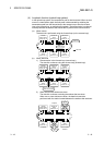
Loopback Loopback
Remote I/O station Remote I/O station Remote I/O station
Forward
SD
Reverse
RD
Reverse
SD
Forward
RD
Forward
SD
Reverse
RD
Reverse
SD
Forward
RD
Communication disabledCommunication disabled
Communication disabled