


5 - 20 5 - 20
MELSEC-Q
5 PARAMETER SETTINGS
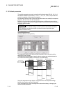
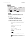
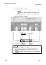
(Refresh parameter setting screen)
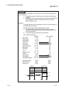
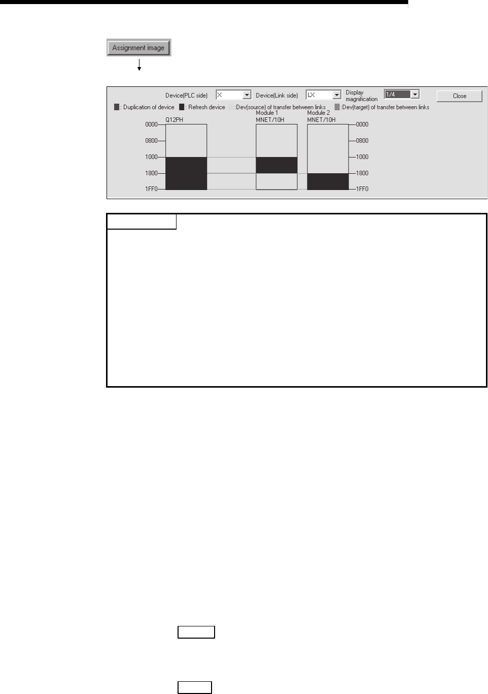
POINT
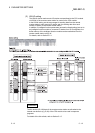
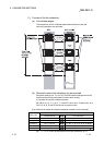
The assignment image diagram can display schematic images of CC-Link IE
Controller Network, CC-Link IE Field Network and MELSECNET/H (network
modules on controller networks, PLC to PLC networks, and remote I/O networks).
Avoid any duplicate settings of the programmable-controller-side devices that are
used for the following.
• Auto refresh parameters of CC-Link modules
• Refresh parameters of CC-Link IE Controller Network modules, CC-Link IE
Field Network modules, and MELSECNET/H network modules
• Auto refresh parameters of intelligent function modules
• Auto refresh using the CPU-shared memory in the multiple CPU system
• I/O numbers used for I/O modules and intelligent function modules
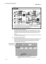
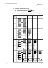
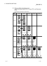
1) Assignment method
Select the device range input method from either Points/Start or
Start/End.
• Default: Start/End
2) Transient transmission error history status
Select whether to overwrite or hold the error history.
• Default: Overwrite
3) Transfer settings on the Link side and the PLC side
Select the device names from the following:
Link side : LX, LY, LB. LW
PLC side : X, Y, M, L, T, B, C, ST, D, W, R, ZR
However, if the link side is LX, any of C, T and ST cannot be selected
on the CPU side.
Set the values for Points/Start/End in 16-point units.
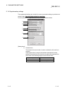
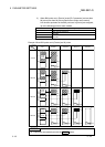
4) Default
button
Select this button to automatically assign the default link devices
according to the number of installed modules.
5) Check
button
Select this button to check if there are any duplicate parameter data
settings.