


2 - 12 2 - 12
MELSEC-Q
2 SYSTEM CONFIGURATION
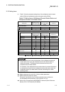
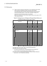
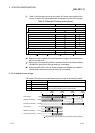
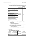
(2) Table 2.8 lists the setting items for the remote I/O module main module for the
remote I/O station (R) and the parameter setting items from the GX Developer.
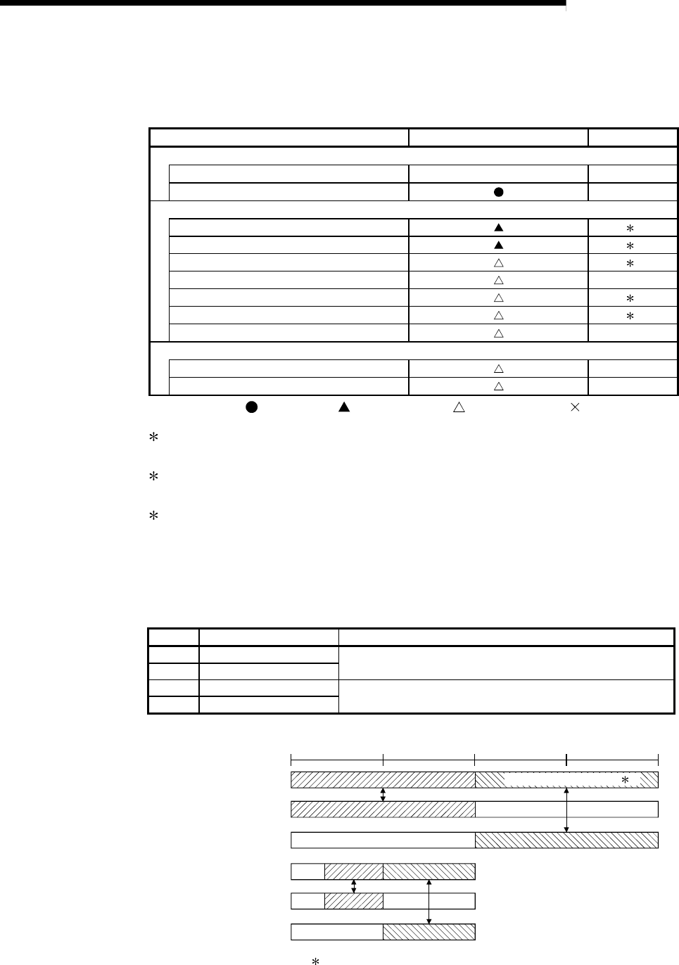
Table 2.8 Remote I/O station setting items
Setting items Remote I/O station (R) Reference
Network module main module switch
STATION NO. 1 to 64 Section 4.2.2
MODE
Section 4.2.2
GX Developer parameter setting
PLC system
4
PLC RAS
4
I/O assignment 4
Operation setting Section 5.2.1
Ethernet setting 5
CC-Link setting 6
Remote password setting
Section 7.12
GX Configurator setting
Initial setting
Section 5.2.1(4)
Auto refresh setting
Section 5.2.1(4)
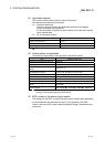
: Always set,
:
Default setting,
:
Set as needed,
:
No need to set
4 : Refer to the User's Manual (Function Explanation, Program Fundamentals) for
the CPU module used.
5 : Refer to the Q Corresponding Ethernet Interface Module User's Manual (Basic)
(SH-080009). Note that the interrupt setting is not available.
6 : Refer to the MELSEC-Q CC-Link System Master/Local Module User's Manual
(SH-080394E). Note that the interrupt setting is not available.
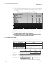
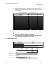
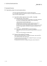
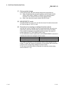
2.4.3 Available device ranges
The remote I/O network can use the following device ranges in the network module.
Device Available range Others
LB 0H to 3FFFH (16384 points)
—
LW 0H to 3FFFH (16384 points)
LX 0H to 1FFFH (8192 points)
The device range (excluding that of I/O module mounted on the host
station) should be assigned to each network module.
LY 0H to 1FFFH (8192 points)
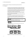
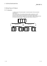
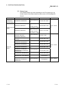
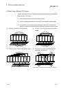
B/W
LB/LWRemote I/O network 2
LB/LW
CPU module
0
3FFF
H
2000
H
3000H
(4096)
1000
H
(8192) (12288) (16383)
Remote I/O network 1
X/Y
LX/LYRemote I/O network 2
LX/LY
CPU module
Remote I/O network 1
Real I/O
1: Expandable by changing from [PLC parameters] - [Device settings]
Extended function area 1