


App - 43 App - 43
MELSEC-Q
APPENDICES
(2) System information
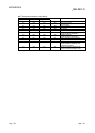
Special Register List
Number Name Meaning Explanation
Set by
(When set)
Corresponding
ACPU
D9
Corresponding
CPU
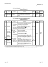
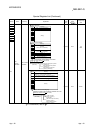
SD200
Status of
switch
Status of CPU
switch
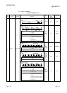
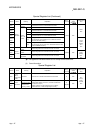
• This register stores the status of the remote I/O module switch in the
following bit pattern.
B15 B4B3 B0
1
Empty
1
Remote I/O module switch status Always 1: STOP
S (Always) New Rem
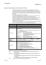
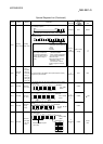
• This register stores the status of the CPU module switches in the
following bit pattern.
B15
B12
B11
B8
B7
B4
B3 B0
Empty
3 2
1
S (Every
END
processing)
New
Qn(H)
QnPH
QnPRH
1
: CPU switch status 0: RUN
1: STOP
2: L.CLR
2
: Memory card switch Always OFF
3
: DIP switch B8 through B12 correspond to SW1
through SW5 of system setting
switch 1.
0: OFF, 1: ON
BD through BF are empty.
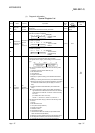
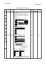
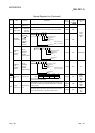
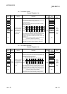
• This register stores the status of the CPU module switches in the
following bit pattern.
B15 B6B5B4B3 B0
Empty
2
1
S (Every
END
processing)
New Q00J/Q00/Q01
1
: CPU switch status 0: RUN
1: STOP
2
: Memory card switch Always OFF
• This register stores the status of the CPU module switches in the
following bit pattern.
B15 B6B5B4B3 B0
Empty
2
1
S (when
RUN/
STOP/
RESET
switch
changed)
New QnU
1
: CPU switch status 0: RUN
1: STOP
2
: Memory card switch Always OFF
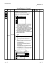
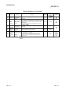
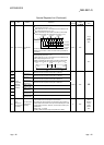
• This register stores the status of the CPU module switches in the
following bit pattern.
B15
B12
B11
B8
B7
B4
B3 B0
Empty
3 2
1
S (Every
END
processing)
New QnA
1
: CPU key
State of switch
0 : RUN
1 : STOP
2 : L.CLR
2 : Memory card switch B4: card A, B5: card B,
0: OFF, 1: ON
3
: DIP switch B8 through B12 correspond to SW1
through SW5 of system setting
switch 1.
B14 and B15 correspond to SW1
and SW2 of system setting switch
2.
0: OFF, 1: ON