


8 - 22 8 - 22
MELSEC-Q
8 TROUBLESHOOTING
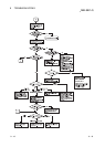
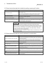
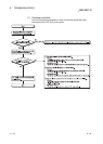
8.2.3 Items checked when data link is disabled by resetting or powering off a station
Check item Checking procedure
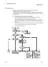
Is the cable wired properly?
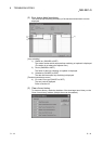
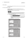
Check the wiring status with GX Developer's network diagnostic loop test.
(Refer to Section 4.10.1.)
In the case of the coaxial bus system, check the coaxial connector connection on each
station and connections between the coaxial cables and coaxial connectors.
Are the cables disconnected?
Check the status of each station to see whether the entire system is faulty or a specific-
station is faulty, and locate the faulty area.
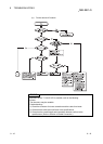
Are the switches of the network modules on all
stations set in the correct position?
Make sure that the mode setting switches of the network modules on all stations are in
the same position.
Is the setting of the link monitoring time sufficient?
Set the link monitoring time to the maximum value and check whether or not data
linking is possible. If the "L ERR" LED of a normal station is lit, check the TIME error
with the GX Developer's network diagnostics.
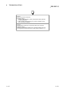
POINT
Do not reset stations which are adjacent each other an optical loop system
(adjacent stations on the wire) simultaneously (resetting by the reset switch of the
remote I/O station or resetting by the key switches of the programmable controller
CPUs of the remote master station and remote sub-master station). Otherwise,
data link may not be able to be established.
If initialization and so on is necessary on adjacent stations simultaneously, turn off
and on the power supply.
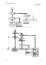
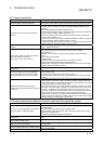
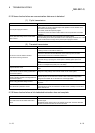
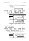
8.2.4 Items checked when data link cannot be performed on a certain station
Check item Checking procedure
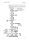
Monitor the transmission status of each station.
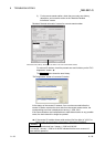
Perform network monitoring of the network diagnostics of GX Developer, check for any
abnormally communicating station and check the loop status. Also, check whether or
not data linking is stopped.
In case of an optical loop system, check the line condition and transmission status of
each station as well, using the loop test of GX Developer's network diagnostics.
Is the network module of the faulty station normal?
Check whether an error or problem has occurred in the CPU module and network
module of the faulty station.
Was the loop error caused by the network module
or the data link cable?
Check whether or not the network module works normally with the self-loopback test of
the offline tests.
Check whether or not the data link cable is normal with the loop test of the offline tests.
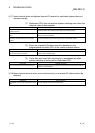
Are the remote master station's parameters
correct?
Check that the total number of link stations is set to the largest number of the
connected stations or more, and check that the stations that cannot communicate are
designated as reserved stations.
Are the control station's parameters normal?
Read the network parameters from the faulty station's CPU module and check that the
network settings such as the network type, start I/O number and network number are
correct.
Are the switch settings of the network module
correct?
Check the station number setting switch and the mode setting switch.
Has any data link cable been disconnected?
Perform the network monitoring or loop test in Network diagnostics of GX Developer to
check the wiring status.