


3 - 35 3 - 35
MELSEC-Q
3 SPECIFICATIONS
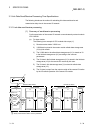
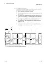
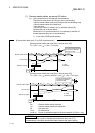
(b) For intelligent function module
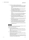
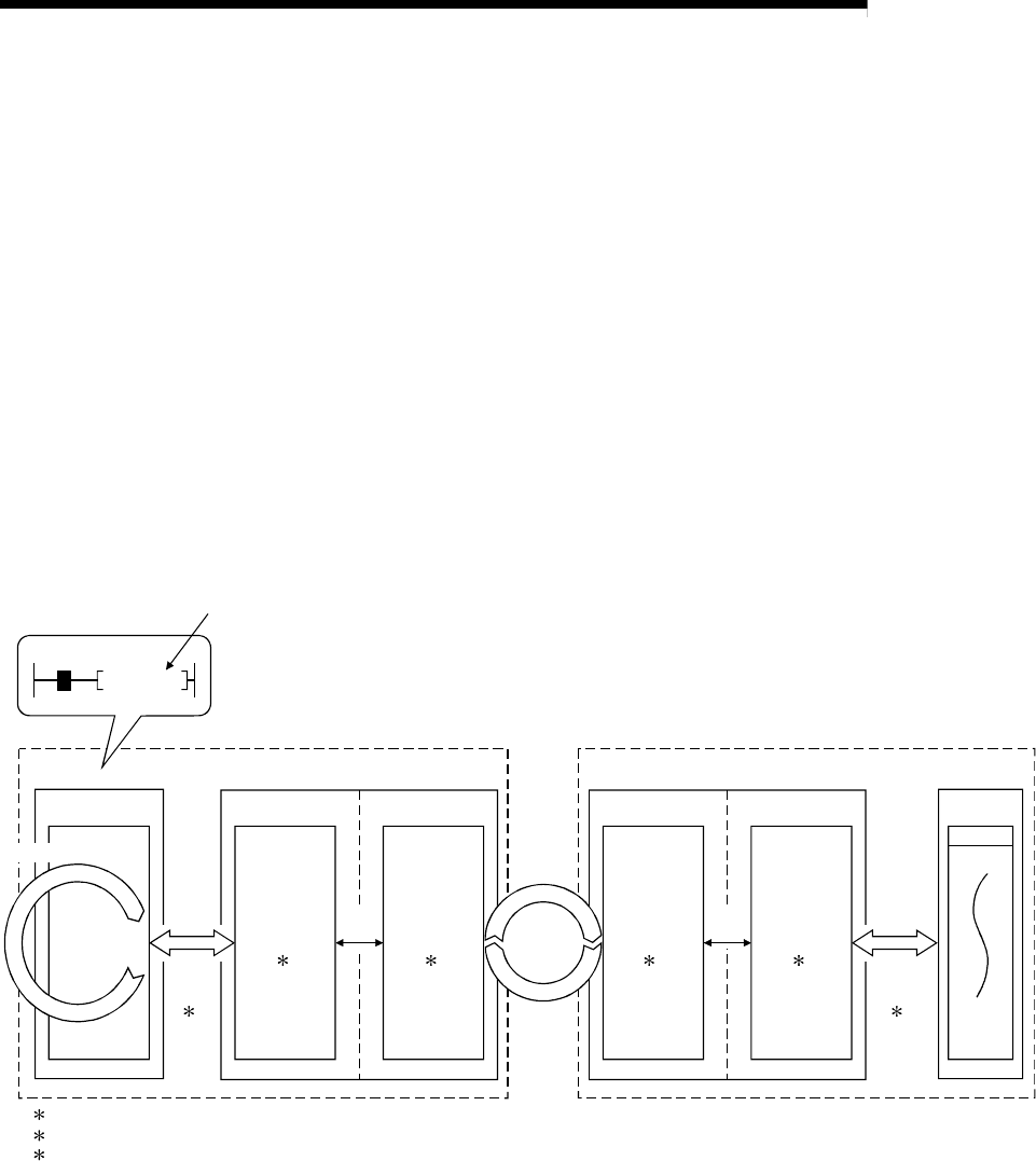
The following provides an example of how the link device (W) on the CPU
module side is sent to an intelligent function module.
1) Data is sent to the remote master station W0.
2) W0 data is stored in the master module refresh data storage area (LW)
by link refresh.
3) The W0 data in the refresh data storage area (LW) is stored as W0 in
the link data storage area (LW) according to the common parameters.
4) The W0 data in the link data storage area (LW) is stored in the link
data storage area (LW) for the remote I/O module by link scan.
5) The W0 data in link data storage area (LW) is stored in refresh data
storage area (LW).
6) The W0 data is written to the remote I/O station intelligent function
module buffer memory address 0 by the automatic refresh settings of
the intelligent function module parameters.
LW LW LW LW(W)W
Address 0
QCPU
1: Set by network refresh parameters.
2: Set by remote master station common parameters.
3: Set by intelligent function module parameter automatic refresh settings.
1)
MOV D0 W0
X0
Buffer
memory
Refresh data
storage area
2
Link data
storage area
2
3) 5)
Device
memory
storage
area
2)
Link
refresh
1
6)
Automatic
refresh
3
Master module Remote I/O module
4)
Link
scan
Sequence scan
Remote master station Remote I/O station
Refresh data
storage area
2
Link data
storage area
2
Intelligent
function module