


8 - 27 8 - 27
MELSEC-Q
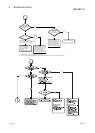
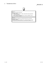
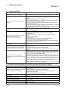
8 TROUBLESHOOTING
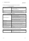
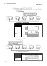
(2) Example of checking SW009C to SW009F
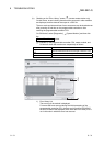
(a) When cables are connected incorrectly at a remote I/O station
(Station No.2)
1) Wiring diagram
Station No. 0 Station No. 1 Station No. 2 Station No. 3 Station No. 4
IN OUT IN OUT IN OUT IN OUT
IN OUT
QJ72LP25-25 QJ72LP25-25QJ72LP25-25QJ72LP25-25QJ71LP21-25QCPU
Cables are connected to wrong connectors
at Station No. 2 (connected OUT-OUT with
Station No. 1 and IN-IN with Station No. 3).
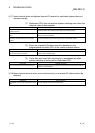
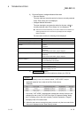
2) SW009C to SW009F status
Station No. SW009C to SW009F status
Station No. 1 Only Station No. 2 (bit 1) is ON or OFF.
0100
b0b1b2b3
0
b15 b4to
SW009C
0SW009D
0SW009E
0SW009F
Station No. 3
Station No. 4
Station No. 2
All stations (bit 0, bit 2, bit 3) than Station No. 2 (bit 1) are ON or OFF.
1011
b0b1b2b3
0
b15 b4to
SW009C
0SW009D
0SW009E
0SW009F
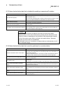
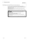
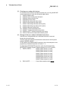
(b) When cables are connected incorrectly at the remote master
station (Station No.0)
1) Wiring diagram
QJ72LP25-25
QJ72LP25-25
QJ72LP25-25QJ72LP25-25
QCPU QJ71LP21-25
Cables are connected to wrong connectors at
Station No.0 (connected IN-IN with Station No.1
and OUT-OUT with Station No.4).
Station No. 0 Station No. 1 Station No. 2 Station No. 3 Station No. 4
IN OUT IN OUT IN OUT IN OUT
IN OUT
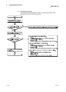
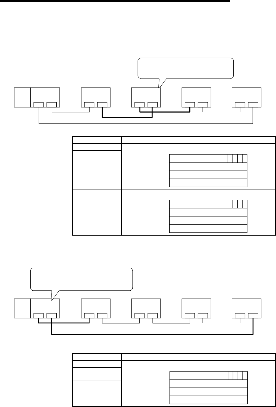
2) SW009C to SW009F status
Station No. SW009C to SW009F status
Station No. 1 All areas for Station No.1 to 4 (bit0 to bit3) turn ON.
1111
b0b1b2b3
0
b15 b4to
SW009C
0
SW009D
0
SW009E
0
SW009F
Station No. 2
Station No. 3
Station No. 4