


7 - 34 7 - 34
MELSEC-Q
7 APPLICATION FUNCTIONS
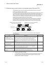
7.11.1 Backup function of master operation on system switching between control system
and standby system
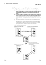
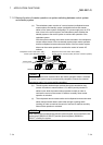
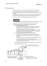
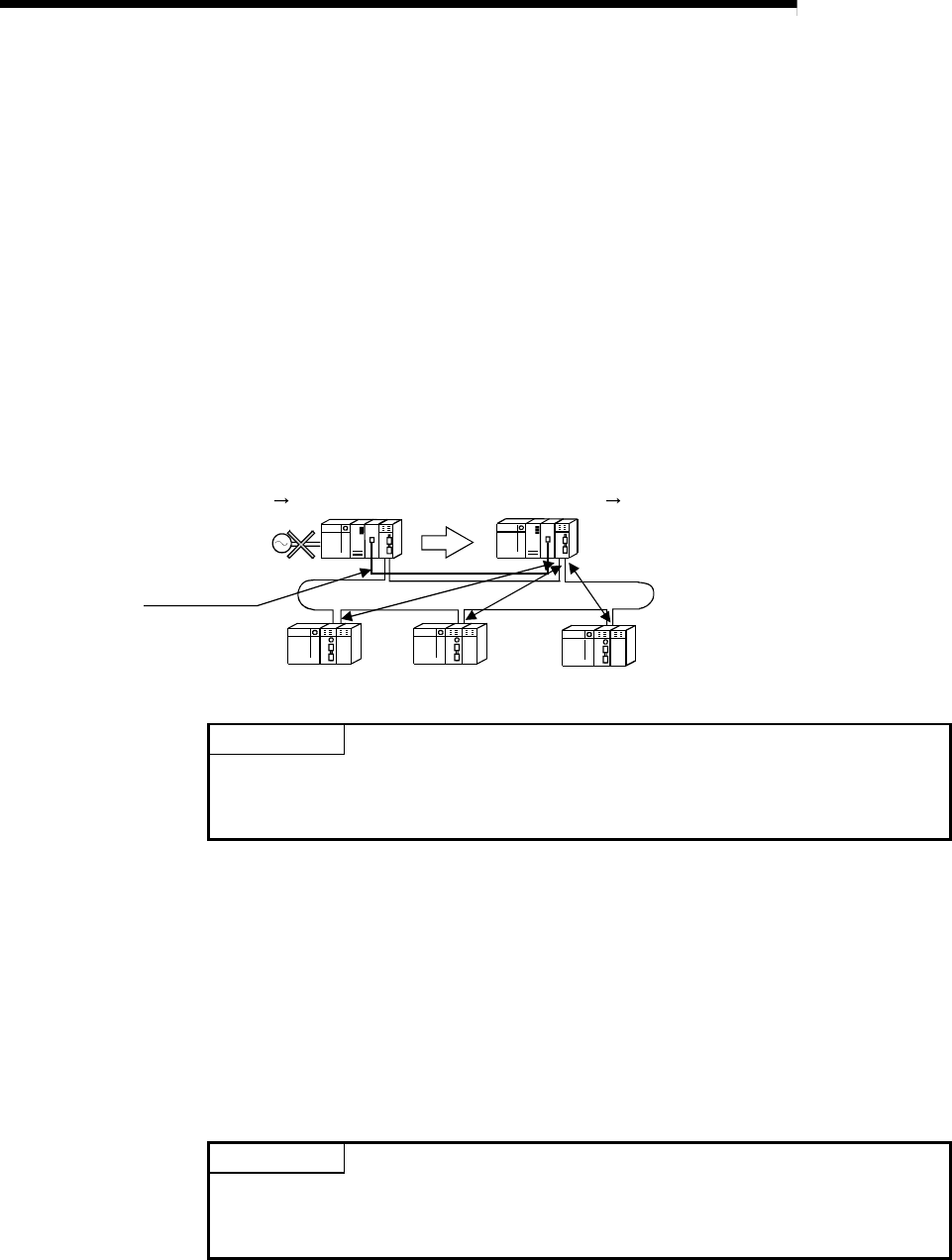
(a) The redundant system consists of a control system (multiplexed remote
master station) and standby system (multiplexed remote sub-master
station) of the same system configuration. If a power supply error or CPU
error occurs in the control system, the Redundant system switches the
standby system to the control system to continue the operation of the
redundant system.
With the system switching, the master module mounted in the multiplexed
remote master station of the new standby system stops master operation
and the multiplexed remote sub-master station of the new control system
takes over the master operation to continue the control of remote I/O
stations.
Multiplexed remote master station (DMR)
Control system Standby system
Multiplexed remote sub-master station (DSMR)
Standby system Control system (execution of master operation)
Remote I/O station (R)
Remote I/O station (R)
Remote I/O station (R)
Tracking cable
POINT
The transient transmission executed when the master operation station is switched
or returns to the system may be unsuccessfully completed. Execute the transient
transmission again if it is unsuccessfully completed.
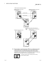
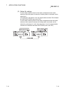
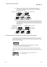
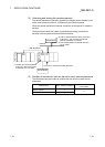
(b) The sub-master station always receives the cyclic transmission data
(remote I/O station to master station: X, B, and W) sent by remote I/O
stations even while the master station operates normally in order to
continue the control of the remote I/O stations smoothly when master
operation is switched.
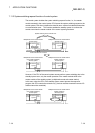
(c) The multiplexed remote master station and multiplexed remote sub-master
station always transfer data to each other through a tracking cable
(tracking) in order to continue the control of remote I/O stations smoothly
when master operation is switched.
POINT
When tracking the link special relay and link special register, do not transfer the link
special relays (SB0020 to SB01FF) and link special registers (SW0020 to
SW01FF) used by the system.