


App - 49 App - 49
MELSEC-Q
APPENDICES
(6) Redundant power supply module information
The special register (SD1780 to SD1789) is valid only for redundant power
supply systems. All bits are set to "0" for single power supply systems.
Special Register List
Number Name Meaning Explanation
Set by
(When set)
Corresponding
ACPU
D9
Corresponding
CPU
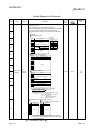
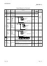
SD1780
Power
supply off
detection
status
Power supply off
detection status
• This register stores status of a redundant power supply module
(Q6
RP) with input power off, in the following bit pattern.
• When the main base unit is not a redundant power main base
unit (Q3
RB), "0" is stored.
Each bit
0: Input power ON status/ No
redundant power supply
module
1: Input power OFF status
b0b7b15
SD1780
*1
b1b8b9
:
:
Input power OFF
detection status of
power supply 2
*1
Input power OFF
detection status of
power supply 1
to to
to to
Main base unit
Extension base unit 1st stage
Extension base unit 7th stage
Main base unit
Extension base unit 1st stage
Extension base unit 7th stage
• In a multiple CPU system, the status is stored only to CPU
module No.1.
S (Every
END
processing)
New
Qn(H)
*2
QnPH
*2
QnPRH
Rem
QnU
*3
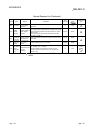
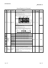
SD1781
Power
supply
failure
detection
Power supply failure
detection status
• This register stores failure detection status of a redundant power
supply module (Q6
RP) in the following bit pattern. (After a
failure is detected on a redundant power supply module, the bit
corresponding to the failed module turns to "0" upon turning off
the module.)
• When the main base unit is not a redundant power main base
unit (Q3
RB), "0" is stored.
b0b7b15
SD1781
Failure detection
status of power
supply 2
*1
Failure detection
status of power
supply 1
*1
b1b8b9
Each bit
0: Redundant power supply
module failure not
detected/No redundant power
supply module
1: Redundant power supply
module failure detected
(Detectable for redundant
power supply module only)
:
:
Main base unit
Extension base unit 1st stage
Extension base unit 7th stage
Main base unit
Extension base unit 1st stage
Extension base unit 7th stage
to to
to to
• In a multiple CPU system, the status is stored only to CPU
module No.1.
S (Every
END
processing)
New
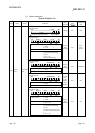
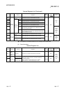
SD1782
Momentary
power
failure
detection
counter for
power
supply 1*1
Momentary power
failure detection count
for power supply 1
• This register counts the number of times of momentary power
failure of the power supply 1/2.
• This register monitors the status of the power supply 1/2
mounted on a redundant power main base unit (Q3
RB) and
counts the number of momentary power failures.
The status of power supply 1/2 mounted on the extension base
unit for redundant power supply system and the redundant type
extension base unit is not monitored.
• When the CPU module starts, the counter of the power supply
1/2 is cleared to "0".
• If the input power to one of the redundant power supply modules
is turned off, the corresponding counter is cleared to "0".
• The counter is incremented by one upon momentary power
failure on the power supply 1 or 2.
• When the main base unit is not a redundant power main base
unit (Q3
RB), "0" is stored.
• In a multiple CPU system, the status is stored only to CPU
module No.1.
• The counter repeats increment and decrement of the value;
0→32767→-32768→0. (The value is displayed within the range
of 0 to 65535 on the device monitor window of GX Developer.)
S (Every
END
processing)
New
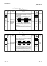
SD1783
Momentary
power
failure
detection
counter for
power
supply 2*1
Momentary power
failure detection count
for power supply 2
S (Every
END
processing)
New
*1: The "power supply 1" indicates the redundant power supply module mounted on the POWER 1 slot of the redundant base unit (Q3 RB/Q6 RB/Q6 WRB).
The "power supply 2" indicates the redundant power supply module mounted on the POWER 2 slot of the redundant base unit (Q3
RB/Q6 RB/Q6 WRB).
*2: This applies to modules whose serial No. (first five digits) is "07032" or later.
However, for the multiple CPU system configuration, this applies to all CPU modules whose serial No. (first five digits) is "07032" or later.
*3: This applies to modules with a serial number (first five digits) of "10042" or later.