


Installation
Document 800-00918 Rev E 27
12/07
Caution The network connector is not designed to be connected directly
with cable or wire intended for outdoor use.
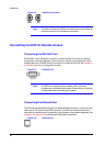
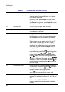
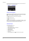
Connecting the RS485 Port
The DVR can be controlled remotely by an external device or control system, such as a
control keyboard, using RS485 half-duplex serial communications signals. The RS485
connector can also be used to control PTZ (pan, tilt, zoom) cameras. Connect the RX-/
TX- and RX+/TX+ of the control system to the TX-/RX- and TX+/RX+ (respectively) of
the DVR. See Chapter 3, Configuration and the PTZ camera or remote controller
manufacturer's manual for configuring the RS485 connection.
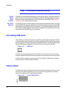
Figure 2-9 RS485 Port
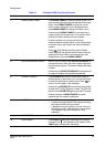
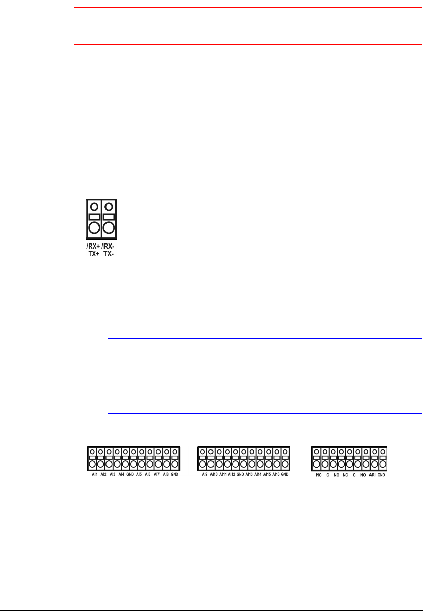
Connecting Alarm Inputs and Outputs
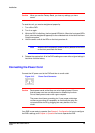
Note To make connections on the Alarm Connector Strip, press and
hold the button and insert the wire in the hole below the button.
After releasing the button, tug gently on the wire to ensure that it
is connected. To disconnect a wire, press and hold the button
above the wire and pull out the wire.
Figure 2-10 Alarm Connector Strip
AI 1 to 16
(Alarm-In)
You can use external devices to signal the DVR to react to events. Mechanical or
electrical switches can be wired to the AI (Alarm-In) and GND (Ground) connectors. The
threshold voltage is 4.3V and should be stable at least 0.5 seconds to be detected. See
Chapter 3, Configuration for configuring alarm input.
GND
(Ground)
Connect the ground side of the Alarm input and/or alarm output to the GND connector.