


Chapter 2 Names and Functions of Parts
2-1 Front Panel 2-3 (E)
a PHONES jack
By connecting stereo headphones with an impedance
of 8 ohms to this jack, you can monitor the sound
during recording, playback, and editing. This
monitors the sound on the channels selected for
monitor output on the currently selected port (using
the PORT SELECT buttons (k) and AUDIO INPUT
SELECT/MONITOR SELECT buttons (l)). Adjust
the monitor volume with the PHONES control (b).
b PHONES control
This adjusts the volume of the output from the
PHONES jack.
c Display selection section
TOTAL/REMAIN (remaining) button
Displays the total time of the files of material held on
the HDD (Sys Total), the remaining available HDD
capacity (Sys Remain), and the time remaining of the
material currently being played/recorded for each
port on the display panel (g). The button lights up
when these are displayed.
FULL/FINE button
Selects the range of the audio level meter on the
display panel (g) for the port currently selected by
the PORT SELECT button (k).
FULL: The level meter range is -60 dB to 0 dB or -40
dB to +20 dB. A setup menu item determines
which of these ranges is used (peak value 0 dB or
+20 dB).
FINE: The level meter display range is magnified, to
display 0.25 dB steps. If the audio level goes
above the maximum display range, the top
segment flashes; if the audio level goes below the
minimum display range, the bottom segment
flashes.
TIMER SEL (time data display select) button
This selects the type of time data displayed on the
display panel (g) for the currently selected port.
When normal time data (one of LTC, VITC, TM1,
and TM2) is displayed, pressing the TIMER SEL
button cycles the display through the sequence LTC
t VITC t TM1 t TM2 t LTC ...
When user bit values are displayed, pressing the
TIMER SEL button toggles between LTC and VITC
user bit information.
TC/UB (timecode/user bits) button
When this button is pressed, turning it on, the user bit
information in the timecode signal on the currently
selected port appears on the display panel.
When the TIMER SEL selection being displayed is
LTC or VITC, then the user bit information from the
corresponding timecode signal is displayed.
Pressing the TC/UB button again when the user bit
information is displayed turns the button off, and
returns the display to normal timecode (i.e. not the
user bits).
d HELP button
If a fault occurs in the system (either Error or Warning
level), press this button to display details of the
problem on the display panel. If more than one error
or warning condition exists simultaneously, press the
HELP button repeatedly to step through the
corresponding displays.
After displaying the error/warning information, the
operation mode of the unit and the cumulative
operating times appear on the display panel in
sequence. Pressing the HELP button when no fault
has occurred displays only this information.
e ERROR/WARNING indicators
SYSTEM indicator
If a fault occurs in the system (either Error or Warning
level), this indicator flashes red. During normal
operation it lights green. When it is flashing red, you
can press the HELP button (d) to display details of
the problem on the display panel.
HDD indicator
This indicator flashes green during access to the
HDD. If a fault (either Error or Warning level) occurs
in a HDD, this indicator flashes red. When it is
flashing red, you can press the HELP button (d) to
display details of the problem on the display panel.
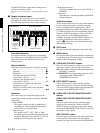
f LED indicators
Operating panel indicators
These indicate which control panel can be operated:
the METER PANEL indicator refers to the unit’s
meter panel, and the CONTROL PANEL indicator
refers to the optional control panel (BKMA-505).
Each indicator lights independently when the
corresponding panel is enabled, and goes off when
the panel is disabled. Further, operable panel settings
can be enabled through the unit’s system setup panel.
525/625 indicators
One of these lights, to show the number of scan lines
in the television standard selected by basic menu item
010 (NTSC: 525 scan lines, 59.94 Hz field frequency;
PAL: 625 scan lines, 50 Hz field frequency).
MENU BANK indicators
The indicator lights that corresponds to the currently
valid SETUP MENU BANK. The SETUP MENU
BANK is selected from the unit’s system set up panel.
When the ERROR/WARNING indicator blinks red, refer to
the “Error Messages” appendix (page A-1).