


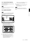

Chapter 3 Preparations
3-4 Setup 3-37 (E)
768
769
770
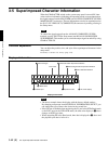
BI
H BLANKING WIDTH P1
H BLANKING WIDTH P2
H BLANKING WIDTH P3
These items select the horizontal blanking width for the video output signal. If
analog blanking was selected, the horizontal blanking width conforms with the
RS170A. The wider the blanking width, the narrower the picture is.
: Digital blanking (narrow)
wide : Analog blanking (wide)
778
BI
SELECTION OF VIDEO/SYNC
DELAY MONITOR
Selects the video output phase that is set for PB/EE on the 013 Setup menu.
: Ignores video signal delays and adds the same sync as the output ref
to the video output. In this case, the picture moves downward when
in EE mode.
SYNC DELAY : Adds a sync signal that is offset to match the video signal delay.
779
780
781
BI
VAR CONROL P1
VAR CONROL P2
VAR CONROL P3
These items set up the video process.
SUB MENU
Y ADD This item specifies whether to forcibly turn Y ADD off in a playback mode other than
normal playback mode (JOG, VAR, SHUTTLE, STILL, etc.).
: Perform Y ADD automatically in any playback mode other than normal
playback mode.
off : Forcibly turn Y ADD off in any playback mode other than normal
playback mode.
ESR When recording or playing back a composite signal, this item specifies whether to
automatically turn the edge subcarrier reducer on/off in accordance with the playback
mode, or to force the edge subcarrier reducer on (in order to play back a non-standard
signal).
: Turn the edge subcarrier reducer on/off in accordance with the playback
mode.
on : Force the edge subcarrier reducer on.
782
783
784
INTERNAL SIGNAL
GENERATOR R1
INTERNAL SINGAL
GENERATOR R2
INTERNAL SINGAL
GENERATOR R3
These items select the test signal that is output from the internal signal generator.
When off:
No test signal is generated, and the unit operates normally.
When not off:
If an INPUT SELECT switch is held down for at least three seconds while lit, all INPUT
SELECT switches light and the internal signal generator operates. The selected test
signal is input to the REC port. It is also possible to record this signal.
: No test signal is generated.
CB100 : 100% color bar signal
CB75 : 75% color bar signal
CB75R : 75% color bar (reverse) signal
BOW : Bowtie signal
PLSBR : Pulse and bar signal
MLTBS : Multi-burst signal
HSWP : HSWP signal (available only in 525 mode)
5STEP : 5-step signal
RAMP : Ramp signal
SH : Shallow ramp signal
RED : Full red signal
GRAY : 50% flat signal
WHITE : 100% flat signal
BB : Black burst signal
SDI : SDI check field signal
NTC7 : NTC7 test signal (available only in 525 mode)
LN330 : Line 330 test signal (available only in 525 mode)
785
786
787
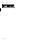
BI
INPUT VIDEO BLANK R1
INPUT VIDEO BLANK R2
INPUT VIDEO BLANK R3
These items turn blanking during the input video signal vertical blanking interval
on and off.
SUB MENU
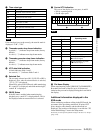
Expansion menu items (Continued)
Item number Display indication Settings Description
narrow
VIDEO DELAY
auto
auto
off