


Chapter 2 Names and Functions of Parts
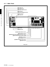
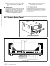
2-2 System Setup Panel 2-7 (E)
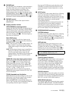
a POWER switch
Set this to the ON position to power on this unit.
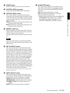
b CONTROL PANEL connector
Connect an optional BKMA-505 Control Panel.
c CONTROL PANEL switch
This selects whether an optional control panel is
connected to the connector on the front panel or to the
connector on the rear panel. If there are control panels
connected to both connectors, this switch determines
which is enabled.
FRONT: Enables the control panel connected to the
connector on the front panel.
REAR: Disables the control panel connected to the
connector on the front panel.
d MEMORY CARD slot
Insert the memory card (sold separately) in this slot.
Settings made on the Setup menu can be saved and
read on a memory card as required.
To remove the card, press the eject button next to the
slot.
Note
Do not eject the memory card while the ACCESS
lamp is lit as this may damage the information on the
memory card.
e SET UP SELECT switch
This selects the number of the menu bank for this
unit’s settings. The menu bank selected by changing
the switch setting becomes effective after the unit is
restarted. However, changes are not effective if made
while the power is off do not become effective the
next time the power is turned on. In order to make the
changes effective, either cycle the power off and on
again, or reboot by means of the FAST REBOOT
item (item number 027) in the basic menu. The
currently valid menu bank is indicated by the MENU
BANK indicators. You can change the settings of the
current menu bank by pressing the MENU button to
display the setup menu. To change the settings of any
other bank, select the bank with the SET UP SELECT
switch while the setup menu is displayed.
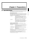
For details of setup menus, see Section 3-4-1, “Basic Menu
Settings” (page 3-18).
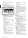
f PANEL SELECT switch
This switch enables or disables each of the meter
panels fitted as standard to this unit and the operation
control panel. The switch settings are as follows.
NONE: Both of the control panels are disabled.
METER PANEL: The meter panel only is enabled.
CONTROL PANEL: The control panel only is
enabled.
BOTH: Both of the control panels are enabled.
g CHARACTER switch
This switch selects whether or not timecodes and
other character information is superimposed on the
video signal output from the MONITOR OUTPUT
connector.
ON: Superimposed information is output.
OFF: Superimposed information is not output.
The factory default setting is ON.
* When the basic menu item ANALOG MONITOR
SUPERIMPOSE (menu 008) is set to “inhibit”,
superimposition cannot be enabled from the
ANALOG COMPOSITE (SUPER) connector.