


Chapter 2 Names and Functions of Parts
2-4 Analog Audio Expansion Box BKMA-570 2-11 (E)
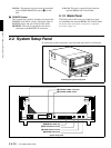
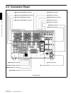
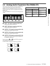
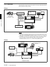
2-4 Analog Audio Expansion Box BKMA-570
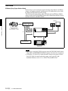
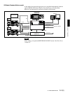
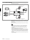
When using analog audio input and output with this unit,
connect the optional Analog Audio Expansion Box
BKMA-570 to the AUDIO I/F connectors on the unit’s
connector panel, then connect to peripheral units via the
BKMA-570.
The optional BKMA-513 is necessary for analog input and
output.
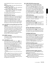
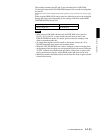
a INPUT 1 (R1 input) connectors (XLR-3-31)
Analog audio inputs to the R1 port.
b INPUT 2 (R2 input) connectors (XLR-3-31)
Analog audio inputs to the R2 port.
c OUTPUT 1 (P1 output) connectors (XLR-3-32)
Analog audio outputs from the P1 port.
d OUTPUT 2 (P2 output) connectors (XLR-3-32)
Analog audio outputs from the P2 port.
e OUTPUT 3 (P3 output) connectors (XLR-3-32)
Analog audio outputs from the P3 port. (Planned for
use with future functions.)
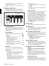
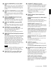
Input connectors (a and b) have LEVEL switches for
each channel as shown below.
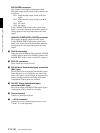
Channel LEVEL switches are set for use as follows:
INPUT
13212
OUTPUT
ab cde
CH1
LEVEL 600Ω
HIGH ON
LOW OFF
CH2
LEVEL 600Ω
HIGH ON
LOW OFF
CH3
LEVEL 600Ω
HIGH ON
LOW OFF
CH4
LEVEL 600Ω
HIGH ON
LOW OFF
Audio Input
Switch Setting
Level Impedance
-60 dBu
(microphone input)
High impedance
(approx. 20 kΩ)
LOW-OFF (lower
position)
+4 dBu (line voice
input)
High impedance
(approx. 20 kΩ)
HIGH-OFF (central
position)
+4 dBu (line voice
input)
600 Ω HIGH-ON (upper
position)