


Chapter 2 Names and Functions of Parts
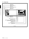
2-4 (E) 2-1 Front Panel
All the LED indicators light when reading from or
saving to the memory card.
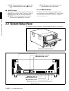
For details, refer to Section 2-2, “System Setup Panel” (page
2-6).
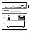
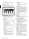
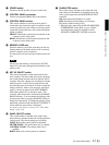
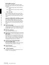
g Display indicators panel
The display panel provides four sets of identical
information, for each of the ports which can be used.
The following figure shows one of these displays.
Time data indication
This shows time data value for the corresponding
port. When you press the MENU button it also shows
setup menu items, and information about Error/
Warning states.
Status indication
This shows the operating status of the port, as follows.
Play................................................................. B
Stopped........................................................... x
Recording ...................................................... z
Variable speed playback (FWD)
at less than 1× speed....................................... B
Variable speed playback (REV)
at less than 1× speed....................................... b
Fast forward or variable speed playback
exceeding 1× speed ........................................ BB
Rewind or variable speed reverse playback
exceeding 1× speed ........................................ bb
Indicators
These show the type of timecode displayed, the
remote/local setting, whether recording is inhibited,
and so forth.
• REC INHIBIT
This appears when recording is inhibited on a
recording port. The recording inhibit setting is
carried out by a setup menu item.
• Time data type
This appears as LTC, VITC, TM1, or TM2,
according to the type of time data currently being
displayed. When user bits from LTC or VITC are
displayed, the UB indicator also appears.
• Remote/local setting
This shows whether the port is set to LOCAL or
REMOTE.
•Port status
When the port is operating normally, the READY
indicator appears.
Audio level meters
These show the audio levels for each of the channels
for the currently displayed port (either recording
levels or playback levels as appropriate). When
playing back material recorded with emphasis on, the
“E” indicator appears for the corresponding channel.
Either the FULL mode display (with two possible
range selections) or the FINE mode display is
available. To change the FULL/FINE selection, use
the FULL/FINE button in the display selection
section (c). Setup menu items determine the scale
and headroom settings.
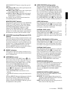
h SET button
Press this button after changing a setup menu item.
i MENU button
Pressing this button lights the indicator, and displays
a setup menu item. Press once again to clear the menu
display without changing the setting.
j VIDEO INPUT SELECT buttons
Press one of these buttons, turning it on, to select the
video input signal to the currently selected port.
SDI: Selects the serial digital video signal input to the
SDI INPUT connector.
COMPOSITE: Selects the analog composite video
signal input to the VIDEO INPUT
(COMPOSITE) connector.
k PORT SELECT buttons
These select the port used for time data display,
audio/video input source selection, and other settings.
The port selected by these buttons also determines the
port output from MONITOR OUTPUT.
l AUDIO INPUT SELECT/MONITOR SELECT
section
AUDIO INPUT SELECT/MONITOR SELECT
buttons
Select the input audio signals or monitor output
signals for the selected port. When the INPUT
SELECT button is lit select the input audio signals,
and when the MONITOR SELECT button is lit select
the monitor output signals.
INPUT SELECT button
Select the type and channel of the audio signal input
to the currently selected port. Press this button,
turning it on, then press the required AUDIO INPUT/
E EOVER OVER OVER OVER
CH15
-60
-40
-30
-20
-10
dB
0
-40
dB
-20
-2
-10
0
10
1
-1
2
20
E E
CH26
-60
-40
-30
-20
-10
dB
0
-40
dB
-20
-2
-10
0
10
1
-1
2
20
E E
CH37
-60
-40
-30
-20
-10
dB
0
-40
dB
-20
-2
-10
0
10
1
-1
2
20
E E
CH48
-60
-40
-30
-20
-10
dB
0
-40
dB
-20
-2
-10
0
10
1
-1
2
20
READY
REC INHI
LTC VITC UB
TM1 TM2
REMOTE LOCAL
Status indication Time data indication
Indicators Audio level meters