


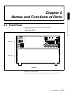

Chapter 2 Names and Functions of Parts
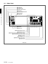
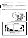
2-1 Front Panel 2-5 (E)
MONITOR SELECT button to assign the type and
channel.
SDI (CH1 to CH4): Select audio signals input to the
SDI INPUT connectors.
AES/EBU (CH1 to CH4): Select audio signals input
to the AUDIO INPUT connectors.
ANALOG (CH1 to CH4): Select the audio signals
that were input at the BKMA-570’s ANALOG
AUDIO INPUT connectors.
If no signal is present on the selected channel the
corresponding button will flash.
MONITOR SELECT buttons
Select the audio signals monitored on the MONITOR
OUTPUT L and R connectors. Press these buttons,
turning them on, then press selected of the AUDIO
INPUT/MONITOR SELECT buttons to assign
channels to the MONITOR OUTPUT L and R
outputs. If you assign more than one of the channels
(channels 1 to 4) to the same monitor output channels,
the channels are mixed to form the monitor output.
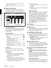
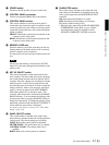
m AUDIO REC (recording)/PB (playback) LEVEL
controls
These adjust the recording or playback levels for each
of the four channels on the currently selected port. If
the currently selected port is a recording port, these
control the recording level, and if a playback port, the
playback level. To make an adjustment, first push in
the knob, so that the PRESET indicator goes off.
While the PRESET indicator is lit, the level is fixed at
the preset value, and cannot be adjusted.
n PB/REC indicators
These light red when the currently selected port is a
recording port, and green when the currently selected
port is a playback port.
o VIDEO/MENU control
While the indicator of the MENU button (i) is lit,
this is used to select an item in the setup menu. For
menu operation, please refer to Section 3-4, “Setup”.
While the indicator of the MENU button is off, this
carries out the VIDEO PROCESS adjustment
according to the VIDEO PROCESS setting mode
currently selected in the VIDEO PROCESS setting
section (p). The adjustment is only possible if both
of the following conditions are met:
• The VIDEO PROCESS control mode is set to
LOCAL
• The PRESET indicator to the top left of the knob is
off
While the PRESET indicator is lit, the preset value for
the currently selected VIDEO PROCESS setting
mode is used, and adjustment is not possible. By
pushing in the knob, the PRESET indicator goes off,
and adjustment is then possible.
p VIDEO PROCESS setting section
The four buttons on the right (VIDEO GAIN,
CHROMA LEVEL, SETUP LEVEL/BLACK
LEVEL, and CHROMA PHASE) are used to select
the corresponding VIDEO PROCESS setting modes.
Press one of the buttons, lighting the indicator, which
shows that the corresponding VIDEO PROCESS
setting mode is selected. The actual adjustment in
each VIDEO PROCESS setting mode is made with
the VIDEO PROCESS control (o). This adjustment
applies only to the currently selected playback port.
VIDEO GAIN button
Press this button, lighting the indicator, to allow the
VIDEO PROCESS control (o) to control the video
output level. The current setting of the video output
level appears around the control knob.
CHROMA LEVEL button
Press this button, lighting the indicator, to allow the
VIDEO PROCESS control (o) to control the
chrominance output level. The current setting of the
chrominance output level appears around the control
knob.
SETUP LEVEL/BLACK LEVEL button
Press this button, lighting the indicator, to allow the
VIDEO PROCESS control (o) to control the setup
level (black level). The current setting of the setup
level (black level) appears around the control knob.
CHROMA PHASE button
Press this button, lighting the indicator, to allow the
VIDEO PROCESS control (o) to control the hue
(burst and chrominance relative phase). The current
setting of the hue appears around the control knob.
The button on the left (the PROCESS CONTROL
button) and the three indicators (the PROCESS
CONTROL MODE indicators) are used to set and
indicate the VIDEO PROCESS control mode.
PROCESS CONTROL button
This sets the VIDEO PROCESS control mode for the
selected port. Each time you press the button, the
control mode cycles through REMOTE, MENU,
LOCAL, REMOTE, and so on. The current mode is
shown by the PROCESS CONTROL MODE
indicators.
PROCESS CONTROL MODE indicators
These show the current VIDEO PROCESS control
mode for the selected port.
REMOTE: The internal digital video processor is
controlled with the HD Digital Video Controller
HKDV-503/900 (sold separately).
MENU: Indicates that the internal video processor is
under control of the Setup menu.