


Chapter 4 Recording & Playback
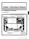
4-2 (E) 4-1 Preparations for Recording
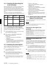
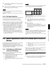
4-1-2 Selecting the Recording Port
to be Controlled
Because the MAV-555SS can handle up to three recording
ports, when making the various settings concerning
recording that are described later in this chapter it is first
necessary to specify which recording port is the target of
the setting. (Settings must be made individually for each
port.)
To select a recording port, press the PORT SELECT
button that corresponds to that port so that the button is lit.
4-1-3 Selecting the Video Signals
Set the VIDEO INPUT SELECT buttons by the following
procedure, according to the video input signals.
1
With the PORT SELECT buttons, select the recording
port to which the setting applies.
2
Press the SDI or COMPOSITE VIDEO INPUT
SELECT button, turning it on.
•SDI button:
to select the signal input to the SDI INPUT
connectors
• COMPOSITE button:
The optional AD/DA converter board BKMA-513
is required when selecting the signal input for the
VIDEO IN (COMPOSITE) connectors.
4-1-4 Selecting the Audio Signals
Set the AUDIO INPUT/MONITOR SELECT buttons as
follows, according to the audio input signals.
1
Press the PORT SELECT button to select the
applicable recording port.
2
Press the INPUT SELECT button, turning it on.
The AUDIO INPUT/MONITOR SELECT buttons
which are lit show the current selection.
3
Use the following buttons to select the input channels.
You can select input sources individually for each
channel.
• SDI CH1 to CH4 buttons:
signals input to the SDI INPUT connectors
(channels 1 to 4)
• AES/EBU CH1 to CH4 buttons:
signals input to the AUDIO INPUT (AES/EBU)
connectors (channels 1 to 4)
• ANALOG CH1 to CH4 buttons:
signals input to the ANALOG AUDIO INPUT
connectors (channels 1 to 4)
* Requires the optional AD/DA Converter Board
BKMA-513 and Analog Audio Extension Unit
BKMA-570.
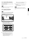
4-1-5 Selecting the Video and Audio
Signals to be Monitored
This section describes how to select the video and audio
signals to be monitored.
Note
The video and audio signals in the monitor output are
those of the currently selected port.
Selecting the video signals to be
monitored
The video signal of the currently selected port is output
from the SDI (SUPER) and ANALOG COMPOSITE
(SUPER) connectors.
Character information is superimposed on the outputs
from these connectors.
For details of settings relating to the superimposed character
information, see Section 3-4-1, “Basic Menu Settings” (page 3-18).
Selecting the audio signals to be
monitored
Using the AUDIO INPUT/MONITOR SELECT buttons,
switch the audio signals output from the PHONES jack,
SDI (SUPER) connector, and MONITOR OUTPUT L/R
connectors, as follows.
1
Press the MONITOR SELECT button, turning it on.
The AUDIO INPUT/MONITOR SELECT buttons
that are lit show the current monitoring selection.
2
Press the corresponding buttons, turning them on, to
select from channels 1 to 4 for the L and R monitoring
channels (a channel can be assigned to both L and R).
Notes
• The monitored audio signal uses the same port as the
video signal.
• Audio signals output from the SDI (SUPER) connector
are as follows:
CH1: Audio monitor output. Same as the Lch signal.
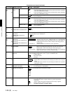
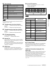
Mode
PORT SELECT
button
Application
Configuration
SS mode R1
Selecting the R1 port
1 input/
1 output
SD mode R2/P3
Selecting the R2 port
2 input /
2 output
3 input /
1 output
R3/P2
Selecting the R3 port
3 input /
1 output