


Chapter 2 Names and Functions of Parts
2-3 Connector Panel 2-9 (E)
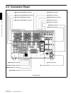
a VIDEO IN (COMPOSITE) connectors (BNC
type)
Input composite video signals (when the BKMA-513
option is installed). The connectors provide a loop-
through connection. A maximum of two inputs are
possible.
b VIDEO OUT (COMPOSITE) connectors (BNC
type)
Output composite video signals (when the BKMA-
513 option is installed). A maximum of two outputs
are possible.
c AUDIO IN (AES/EBU Digital Audio Input)
connectors (BNC type)
These jacks input digital audio signals in the AES/
EBU format. Up to three inputs can be supported.
d AUDIO OUT (AES/EBU) connectors (BNC
type)
These jacks output digital audio signals in the AES/
EBU format. Up to three outputs can be supported.
e REFERENCE connectors (BNC type)
Input a reference video signal. This may be a video
signal with chrominance burst (VBS) or a
monochrome video signal (VS).
The connectors provide a loop-through connection.
f TIME CODE IN (Time Code Input) connectors
(BNC type)
This is the input jack that is used when recording time
codes from an external device. This jack connects to
the time code output jack on the external device.
The setting that indicates which of the inputs, either
SYSTEM or R1 (R2), in each recording port is to be
used for time code recording is make in the “LTC
SELECT” expansion menu item (menu 670, 671).
(However, when the configuration is 3 input/1 output,
SYSTEM is always used at the R3 port.)
Note
The TIME CODE IN (SYSTEM) jack supports only
a 1× time code signal. The error message “TM
Warning LTC” appears if any other signal is input.
g TIME CODE OUT connectors (BNC type)
These connectors output playback time codes.
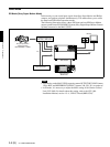
h ETHERNET
1)
(10BaseT) connector
In order to control the MAV-555SS from an external
device that is connected via Ethernet, connect this
connector to the external device with an Ethernet
cable.
When using a LAN cable: For safety, do not connect
to the connector for peripheral device wiring that
might have excessive voltage.
1)
Ethernet is a registered trademark of the XEROX
Corporation.
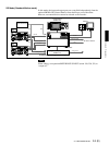
i REMOTE (Remote Control Input/Output)
Connectors
REMOTE IN connector (R1, P1, R2/P3, R3/P2,
SPARE)
When controlling the MAV-555SS through an
external device, use the 9-pin remote control cable to
connect this connector to the external device.
REMOTE IN/OUT connector (1, 2)
When controlling an external device from the MAV-
555SS, use the 9-pin remote control cable to connect
the external device to this connector.
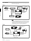
VIDEO CONTROL connector (D-SUB 25 pins)
When controlling the internal digital video processor
from a remote location, connect the HD digital video
controller HKDV-503/900 (sold separately) to this
connector.
For details, refer to the installation manual.
REMOTE PARALLEL I/O connector (D-SUB
50 pins)
The remote control signals from an external device
are connected to this connector.
For details, refer to the installation manual.
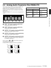
j AUDIO I/F connector
Connect to the optional BKMA-570 Analog Audio
Expansion Unit.
For information on the BKMA-570 connectors, refer to Section
2-4, “Analog Audio Expansion Box BKMA-570” (page 2-11).
k MONITOR OUT connectors (BNC type, XLR-
3-31)
Output video and audio monitor signals for the port
currently selected on the front panel. The XLR
connectors (L/R) output the audio monitor signal, and
the SDI and ANALOG connectors output a video
signal including superimposed information.
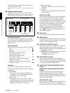
Audio monitor output connectors
There are two audio outputs, L and R. The channels
output are selected with the meter panel’s MONITOR
SELECT buttons and AUDIO INPUT/MONITOR
SELECT buttons.