Chapter 3 Preparations
3-38 (E) 3-4 Setup
785
786
787
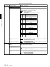
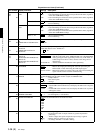
BI
when in 525
mode
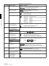
All Lines : Specify line blanking for each line.
throu : Turn off blanking for all lines that can be specified in this menu, regardless
of the other SUB MENU settings.
blank : Turn on blanking for all lines that can be specified in this menu, regardless
of the other SUB MENU settings.
Lines 10 .. 20
: Do not perform blanking.
blank : Perform blanking.
when in 625
mode
All Lines : Specify line blanking for each line.
throu : Turn off blanking for all lines that can be specified in this menu, regardless
of the other SUB MENU settings.
blank : Turn on blanking for all lines that can be specified in this menu, regardless
of the other SUB MENU settings.
Lines 7 .. 22
: Do not perform blanking.
blank : Perform blanking.
788
789
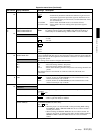
BI
VIDEO INPUT AGC/MANUAL
R1
VIDEO INPUT AGC/MANUAL
R2
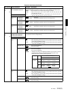
These items select AGC ON/OFF (MANUAL) for the input video signal.
MANUAL
791
792
BI
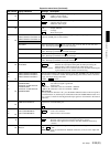
VIDEO INPUT MANUAL
LEVEL R1
VIDEO INPUT MANUAL
LEVEL R2
These items specify the input video signal level when VIDEO INPUT AGC/MANUAL
(menu 788, 789) are set to “MANUAL.”
0 .. .. FF
794
795
796
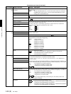
BI
SELECTION OF VIDEO/SYNC
DELAY P1
SELECTION OF VIDEO/SYNC
DELAY P2
SELECTION OF VIDEO/SYNC
DELAY P3
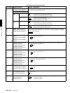
Selects the VIDEO OUTPUT phase for the EE mode.
: Adds the same SYNC to the VIDEO OUTPUT as to OUTPUT REF
while ignoring the video signal delay. In this case, in EE mode, an
NTSC image moves down 4 lines, whereas a PAL image moves
down 6 lines.
SYNC DELAY : Attaches SYNC that matches the video signal delay.
797
BI
VIDEO EDIT PREVIEW
SWITCHER
Sets the output phase of the video playback signal for the Edit Preset status.
: Matches the output phase during EE. Set when previewing the
MAV-555SS or while monitoring the VTR output signal.
external switcher : Matches the internal or external video code. Set when switching the
signal with the external switcher and Previewing.
801
B
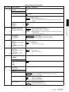
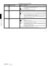
AUDIO MONITOR OUTPUT
MIXING
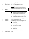
This item sets the mixing method for the digital audio or analog audio that is output from
the SDI (SUPER) jack, the audio monitor out jack, and PHONE OUT.
add : Simple addition
: Root mean square
average : Average
802
BI
METER SCALE This item sets the mode for the display of the digital audio level.
: Assume 0dB as the maximum level, and display the audio level as negative
values.
ref 0dB : Assume 0dB as the reference level, and display the audio level as positive
and negative values.
803
BI
AUDIO LEVEL METER
DIMMER CONTROL
This item sets the brightness of the audio level meter.
.. 7 : 0 is the brightest, 7 is the darkest.
804
BI
AUDIO HEAD ROOM This item sets the headroom for the audio level meter.
18 dB
16 dB
14 dB
12 dB
15 dB
9 dB
805
BI
DIGITAL JOG SOUND This item turns the digital jog sound on and off.
off : Digital channel audio is output without any speed compensation
processing.
: Audio is output after speed compensation processing is applied.
muting : Muting while jog operation is in progress.
+1.0 : At settings other than +1.0, JOG is muting.
Expansion menu items (Continued)
Item number Display indication Settings Description
–
throu
–
throu
AGC
40
VIDEO DELAY
internal
rms
peak 0dB
0
20 dB
on


