159
Chapter 5: Reference
The Sampling Tab
as the sampling clock.
Generally, the state mode sampling clock is taken from the
signals that clock valid data in the device under test.
See Also “Selecting the State Mode (Synchronous Sampling)” on page 46
“In Either Timing Mode or State Mode” on page 53
Sampling Positions Dialog
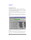
The Sampling Positions dialog lets you position the logic analyzer's
setup/hold window (or sampling position) so that data on high-speed
buses is captured accurately, in other words, so that data is sampled
when it is valid.
When the device under test's data valid window is less than 2.5 ns
(roughly, for clock speeds >= 200 MHz), it's easiest to use eye finder
to locate the stable and transitioning regions of signals and to
automatically adjust sampling positions.
When the device under test's data valid window is greater than 2.5 ns
(roughly, for clock speeds < 200 MHz), it's easiest to adjust the
sampling position manually, without using the logic analyzer to locate
the stable and transitioning regions of signals.
• “Sampling Positions Tab” on page 160
• “Eye Finder Run Messages” on page 162
• “Eye Finder Info Messages” on page 165
• “Eye Finder Load/Save Messages” on page 167
• “Eye Finder Setup Tab” on page 169
• “Eye Finder Advanced Settings Dialog” on page 170
• “File Info Tab” on page 171
See Also “Understanding State Mode Sampling Positions” on page 256
“Selecting the State Mode (Synchronous Sampling)” on page 46


