


Appendix B - Wireless Technology
169
MVP-8400i 8.4" Modero® ViewPoint® Touch Panel with Intercom
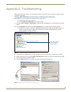
It may take a minute for the panel to detect the new connection and send a signal to the PC (indicated by a
green System Connection icon). If this is your first time installing the USB driver, a USB driver installation
popup window appears on the PC.
9. Complete the USB driver installation process by clicking Yes and then installing the new AMX USB LAN LINK
when told that a new USB device was found. This action accepts the installation of the new AMX USB driver.
10. Reboot the panel. Once restarted, the panel is now configured to communicate directly with the PC.
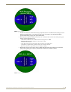
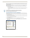
11. Launch the Certificate Upload Utility and confirm the utility has detected the new USB connection to the panel:
Click on the Local Address field's drop-down arrow.
Confirm the new USB entry shows up in the list as: 10.XX.XX.1.
How to Upload a Certificate File
1. Install the latest AMX USB LAN LINK driver onto your computer by installing the latest versions of either
TPDesign4 or NetLinx Studio2. This USB driver prepares your computer to properly communicate with a directly
connected G4 touch panel (MVP/CV7/CV10).
Refer to Step 1 from within the previous Step 1: Setup the Panel and PC for USB Communication section on
page 168.
2. Access the target panel's Protected Setup firmware page and configure the USB communication parameters.
Refer to Step 2 from within the previous Step 2: Confirm the Installation of the USB Driver on the PC section
on page 168.
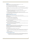
3. With the panel successfully communicating with target computer, launch the Certificate Upload Utility.
Familiarize yourself with the User Interface options (Certificate Utility User Interface).
4. Locate your certificate file by using the Browse button and navigating to the desired file type.
5. Use the drop-down arrow in the Local Address field to select communication through either the computer's Ethernet
port (Internet communication) or via the USB port (direct connection). If using an Ethernet connection skip to step
8.
6. For a USB connection, select the 10.XX.XX.1 IP Address which corresponds to the virtual IP Address assigned to
the USB connection port on the computer.
7. For a USB connection, navigate to the Add IP Address field (bottom-right of the interface) and enter a value of 1
greater than the virtual USB IP Address.
For example: If the virtual USB IP Address is 10.0.0.1 then you would add an address for the directly
connected panel of 10.0.0.2 (this is one greater than the USB address value detected by the utility).
You can send a certificate to ONLY ONE directly connected panel (via USB). If using the Ethernet port's
IP Address, you can send a server certificate to multiple target panels.
8. For an Ethernet IP Address connection, select the IP Address which corresponds to the local computer's Ethernet
address.
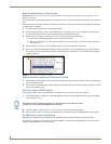
9. Navigate to the Add IP Address field (bottom-right of the interface) and enter the IP Addresses of the various target
touch panels.
10. Click the Add button to complete the entry and add the new IP Address to the listing of available device IP
Addresses. Repeat this process for all subsequent device IP Addresses.
11. Once your list is complete, click on the File drop-down menu and select the Save option to launch a Save dialog
where you can assign a name to the current list of addresses and then save the information (as a TXT (text) file) to a
known location.
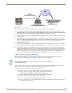
The mini-USB connector MUST be then plugged into an already active panel before
the PC can recognize the connection and assign an appropriate USB driver. This
driver is part of both the NetLinx Studio and TPDesign4 software application
installations.