


Upgrading MVP Firmware
34
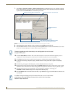
MVP-8400i 8.4" Modero® ViewPoint® Touch Panel with Intercom
Step 1: Configure the panel for a USB Connection Type
1. After the installation of the USB driver has been completed, confirm the proper installation of the large Type-A
USB connector to the PC's USB port, and restart your machine.
2. After the panel powers-up, press and hold the two lower buttons on both sides of the display for
3 seconds to continue with the setup process and proceed to the Setup page.
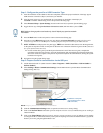
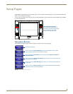
3. Select Protected Setup > System Settings (located on the lower-left) to open the System Settings page.
4. Toggle the blue Type field (from the Master Connection section) until the choice cycles to USB.
5. Press the Back button on the touch panel to return to the Protected Setup page.
6. Press the on-screen Reboot button to both save any changes and restart the panel. Remember that the panel’s
connection type must be set to USB prior to rebooting the panel and prior to inserting the USB connector.
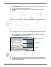
7. ONLY AFTER the unit displays the first panel page, THEN insert the mini-USB connector into the Program Port
on the panel. It may take a minute for the panel to detect the new connection and send a signal to the PC (indicated
by a green System Connection icon).
If a few minutes have gone by and the System Connection icon still does not turn green, complete the
procedures in the following section to setup the Virtual Master and refresh the System from the Online Tree.
This action sends out a request to the panel to respond and completes the communication (turning the System
Connection icon green).
8. Navigate back to the System Settings page.
Step 2: Prepare Studio for communication via the USB port
1. Launch NetLinx Studio 2.x (default location is Start > Programs > AMX Control Disc > NetLinx Studio 2 >
NetLinx Studio 2).
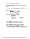
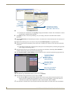
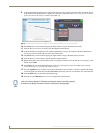
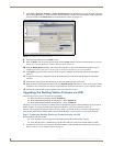
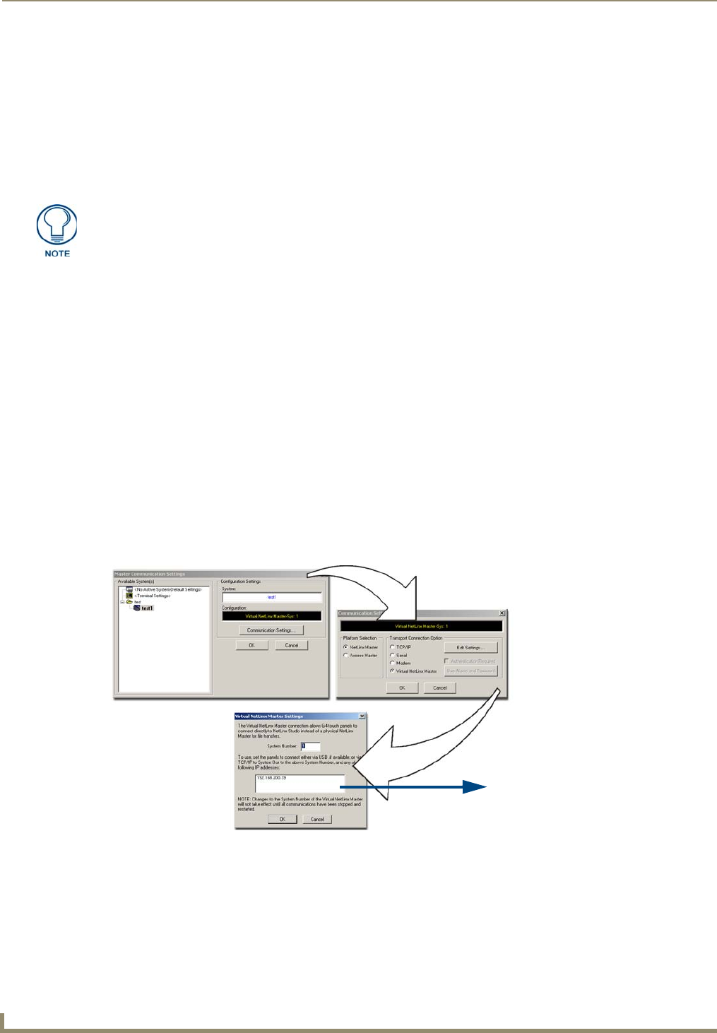
2. Select Settings > Master Communication Settings, from the Main menu to open the Master Communication
Settings dialog (
FIG. 35).
3. Click the Communications Settings button to open the Communications Settings dialog.
4. Click on the NetLinx Master radio button (from the Platform Selection section) to indicate that you are working as
a NetLinx Master.
5. Click on the Virtual Master radio box (from the Transport Connection Option section) to indicate you are wanting
to configure the PC to communicate directly with a panel. Everything else such as the Authentication is greyed-out
because you are not going through the Master’s UI.
ALL fields are then greyed-out and read-only, but still display any previous network
information.
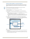
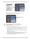
FIG. 35 Assigning Communication Settings for a Virtual Master
IP Address of computer
(not needed as this is a direct
USB connection)