


Configuring Communications
26
MVP-8400i 8.4" Modero® ViewPoint® Touch Panel with Intercom
Configure a Virtual NetLinx Master using NetLinx Studio
A Virtual NetLinx Master (VNM) is used when the target panel is not connected to a physical NetLinx Master. In this
situation, the PC takes on the functions of a Master via a Virtual NetLinx Master. This connection is made by either using
the PC’s Ethernet Address (via TCP/IP using a known PC’s IP Address as the Master) or using a direct mini-USB
connection to communicate directly to the panel.
Before beginning:
1. Verify the panel has been configured to communicate via USB within the System Settings page and that the USB
driver has been properly configured. Refer to the previous section for more information.
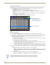
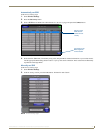
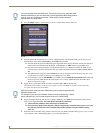
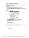
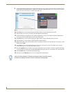
2. In NetLinx Studio, select Settings > Master Communication Settings, from the Main menu to open the Master
Communication Settings dialog (
FIG. 27).
3. Click the Communications Settings button to open the Communications Settings dialog.
4. Click the NetLinx Master radio button (from the Platform Selection section).
5. Click the Virtual Master radio button (from the Transport Connection Option section).
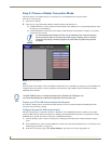
6. Click the Edit Settings button to open the Virtual NetLinx Master Settings dialog (FIG. 27).
7. Enter the System number (default is 1).
8. Click OK to close all open dialogs and save your settings.
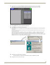
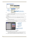
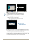
9. Click the OnLine Tree tab in the Workspace window to view the devices on the Virtual System.
10. Right-click on Empty Device Tree/System and select Refresh System to re-populate the list.
The panel will not appear as a device below the virtual system number (in the Online Tree tab) until both the
system number (default = 1) is entered into the Master Connection section of the System Settings page and the
panel is restarted.
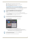
The Connection status turns green after a few seconds to indicate an active USB connection to the PC (Virtual
Master).
If the System Connection icon does not turn green, check the USP connection and communication settings
and refresh the system.
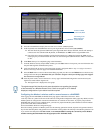
FIG. 27 Assigning Communication Settings for a Virtual Master
(not needed as this is a direct
USB connection)
IP Address of computer