


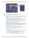

NXA-CFSP Compact Flash
8
MVP-8400i 8.4" Modero® ViewPoint® Touch Panel with Intercom
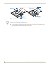
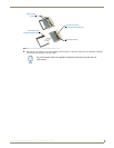
3. Grasp the bottom rim of the rear housing just above the MVP interface connector, and carefully pull the bottom rim
away from the IR Emitter and up, to expose the internal components.
4. Remove the trim from the top rim of the circuit board (FIG. 5).
Removing the Installed Card
1. Discharge any static electricity from your body by touching a grounded metal object and then locate the card slot on
the main circuit board (FIG. 6).
2. Place the circuit board on a flat level surface so that the IR Emitters are pointing away from you (FIG. 6).
3. Insert the tip of a grounded flat-head screwdriver into one of the card removal grooves (located on either side of the
existing card), and gently pry it out of the slot (
FIG. 7). Repeat this process on the opposite card removal groove.
This alternating action causes the card to "wiggle" away from the on-board connector pins.
4. Slip your finger into the gap between the card and the circuit board and firmly grab the card by its sides, then
carefully pull it up and out of the slot. An angular removal of the card is required because one of the housing’s latch
attachments blocks the slot opening.
Installing the Compact Flash Upgrade Card
1. Discharge any static electricity from your body by touching a grounded metal object and then locate the memory
card slot on the main board (A in FIG. 6).
2. Place the circuit board on a flat level surface so that the IR Emitters are pointing away from you (FIG. 6).
3. Insert the tip of a grounded flat-head screwdriver into one of the card removal grooves (located on either side of the
existing Compact Flash card), and gently pry it out of the slot (
FIG. 7). Repeat this process on the opposite card
removal groove. This alternating action causes the pre-existing card to "wiggle" away from the on-board connector
pins.
4. Slip your finger into the opening (between the connector pins and the card resulting from step 3) and push the card
out.
5. Finish the process by firmly gripping the exposed sides of the card and pulling it out (FIG. 7). USE CARE WHEN
HANDLING THE CARD.
use care when pulling up on the card.
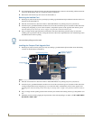
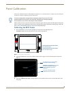
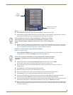
FIG. 6 Location and orientation of the Compact Flash cards (both MVP panels)
Compact Flash
Card removal grooves
IR Emitters
Internal circuit board
(top view - detail)
A B
Wireless Interface
card
card