


258
CHAPTER 17 Serial I/O
■
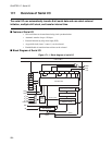
Operation Mode of Serial I/O
In terms of the serial I/O operation mode, there are two types, namely, internal shift clock mode and
external shift clock mode depending on the shift clock type, and these are specified by the SCMR. Mode
switching and clock selection should be executed while the serial I/O is stopped (ST bit of SCR = 0).
●
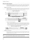
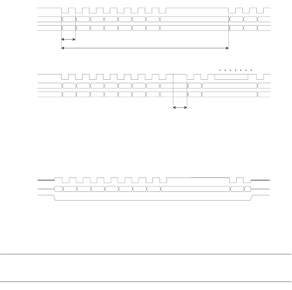
Internal shift clock mode
Operated by the internal clock, and outputs the shift clock with 50% duty from the SCK pin as the
synchronous timing output. In terms of data, 1-bit transfers are carried out per clock, and data for the
number of bytes that have been set for the SCBR is transferred sequentially at set intervals.
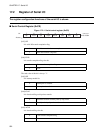
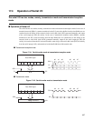
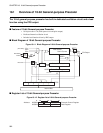
Figure 17.4-3 Interval mode
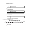
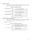
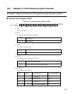
Figure 17.4-4 No interval mode
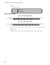
[Automatic transfer mode by chip select]
Setting "1" to chip select enable (CSE) bit enables control for the starting and stopping of transfers by
the chip select input (XCS) pin. When serial transfer starts at the falling of the XCS pin, and the XCS
pin rises before transfer for the number of bytes set has ended, serial transfer will be forcibly
terminated. When the XCS pin is "H" level, both the SCK and SO pins will have high impedance.
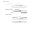
Figure 17.4-5 Chip select transfer mode
●
External shift clock mode
Transfers 1-bit data per clock in synchrony with the external shift clock input from the SCK pin. Select
other than No Interval (IC1, 0=1, 1) as the interval specification in this case. When No Interval is selected,
communication cannot be carried out correctly.
Note:
Do not write SCR, SCMR, or SCBR during serial I/O operation under either mode.
SO
SI
SCK
#0 #1 #2 #3 #4 #5 #6 #7 #0 #1 #2
Tclk
Tint
Tclk: Clock cycle
Tint: Interval
SO
SI
SCK
#0 #1 #2 #3 #4 #5 #6 #7 #0 #1 #7
Tclk
XCS
SO
SCK
#0 #1 #2 #3 #4 #5 #6 #7 #0 #1
start stop