


283
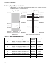
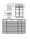
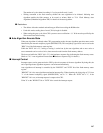
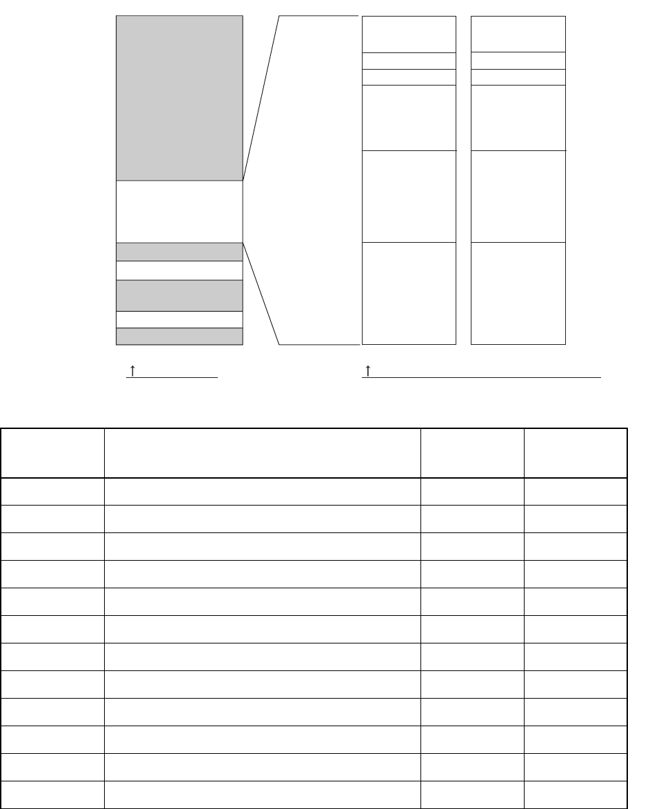
Figure 21.1-4 Memory Map and Sector construction (MB91F192)
Table 21.1-2 Sector address table (MB91F192)
Sector address Address range
Corresponding
bit position
Sector capacity
SA0 000A0000-1h to 000BFFFC-Dh (MSB side 16-bit) Bit31 to 16 64 Kbytes
SA1 000C0000-1h to 000DFFFC-Dh (MSB side 16-bit) Bit31 to 16 64 Kbytes
SA2 000E0000-1h to 000EFFFC-Dh (MSB side 16-bit) Bit31 to 16 32 Kbytes
SA3 000F0000-1h to 000F3FFC-Dh (MSB side 16-bit) Bit31 to 16 8 Kbytes
SA4 000F4000-1h to 000F7FFC-Dh (MSB side 16-bit) Bit31 to 16 8 Kbytes
SA5 000F8000-1h to 000FFFFC-Dh (MSB side 16-bit) Bit31 to 16 16 Kbytes
SA6 000A0002-3h to 000BFFFE-Fh (LSB side 16-bit) Bit15 to 00 64 Kbytes
SA7 000C0002-3h to 000DFFFE-Fh (LSB side 16-bit) Bit15 to 00 64 Kbytes
SA8 000E0002-3h to 000EFFFE-Fh (LSB side 16-bit) Bit15 to 00 32 Kbytes
SA9 000F0002-3h to 000F3FFE-Fh (LSB side 16-bit) Bit15 to 00 8 Kbytes
SA10 000F4002-3h to 000F7FFE-Fh (LSB side 16-bit) Bit15 to 00 8 Kbytes
SA11 000F8002-3h to 000FFFFE-Fh (LSB side 16-bit) Bit15 to 00 16 Kbytes
*1: The mounted flash memory is little endian, but it is converted to big endian by the FR-CPU interface circuit. This
conversion function does not work during access by the ROM writer, so mapping is different from CPU mode.
SA5(16Kbyte) SA11(16Kbyte)
SA4(8Kbyte) SA10(8Kbyte)
SA3(8Kbyte) SA9(8Kbyte)
SA2(32Kbyte) SA8(32Kbyte)
SA0(64Kbyte) SA6(64Kbyte)
31 16 015
FFFFFFFFH
000FFFFFH
000A0000H
00080800H
000007C0H
00000000H
000FFFFC-DH
000F8000-1H
000F4000-1H
000E0000-1H
000C0000-1H
000A0000-1H
000FFFFE-FH
000F4002-3H
000E0002-3H
000C0002-3H
000A0002-3H
00080000H
000F0000-1H
000F0002-3H
SA1(64Kbyte) SA7(64Kbyte)
000F8002-3
H
MSB side 16bit LSB side 16bit
Flash memory region
Internal RAM region
Memory map Sector construction (SA=Sector address)
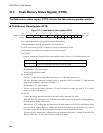
Status register