292
CHAPTER 21 Flash Memory
21.5 Auto Algorithm Execute State
This flash memory has hardware that notifies the internal flash memory operation
status and operation completion for outside of the flash memory to execute the write/
erase flow by auto algorithm. One is a hardware sequence flag, and the other is the
ready/busy signal.
■
Ready/Busy Signal (RDY/BUSYX)
The flash memory has a ready/busy signal as well as a hardware sequence flag as a means to notify whether
the internal auto algorithm is being executed or has finished. This ready/busy signal is connected to the
flash memory interface circuit, and can be read as the "RDY" bit of the flash memory status register.
Interrupt requests can be also generated to the CPU by the rising of the ready/busy signal. (Refer to "21.2
Flash Memory Status Register (FSTR)" for details).
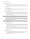
When the read value of the "RDY" bit is "0", the flash memory is being written on or erased. In this case,
neither write nor erase commands will be accepted. When the read value of the "RDY" bit is "1", the flash
memory is on wait state to be read/written on or erased.
■
Hardware Sequence Flag
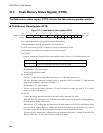
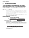
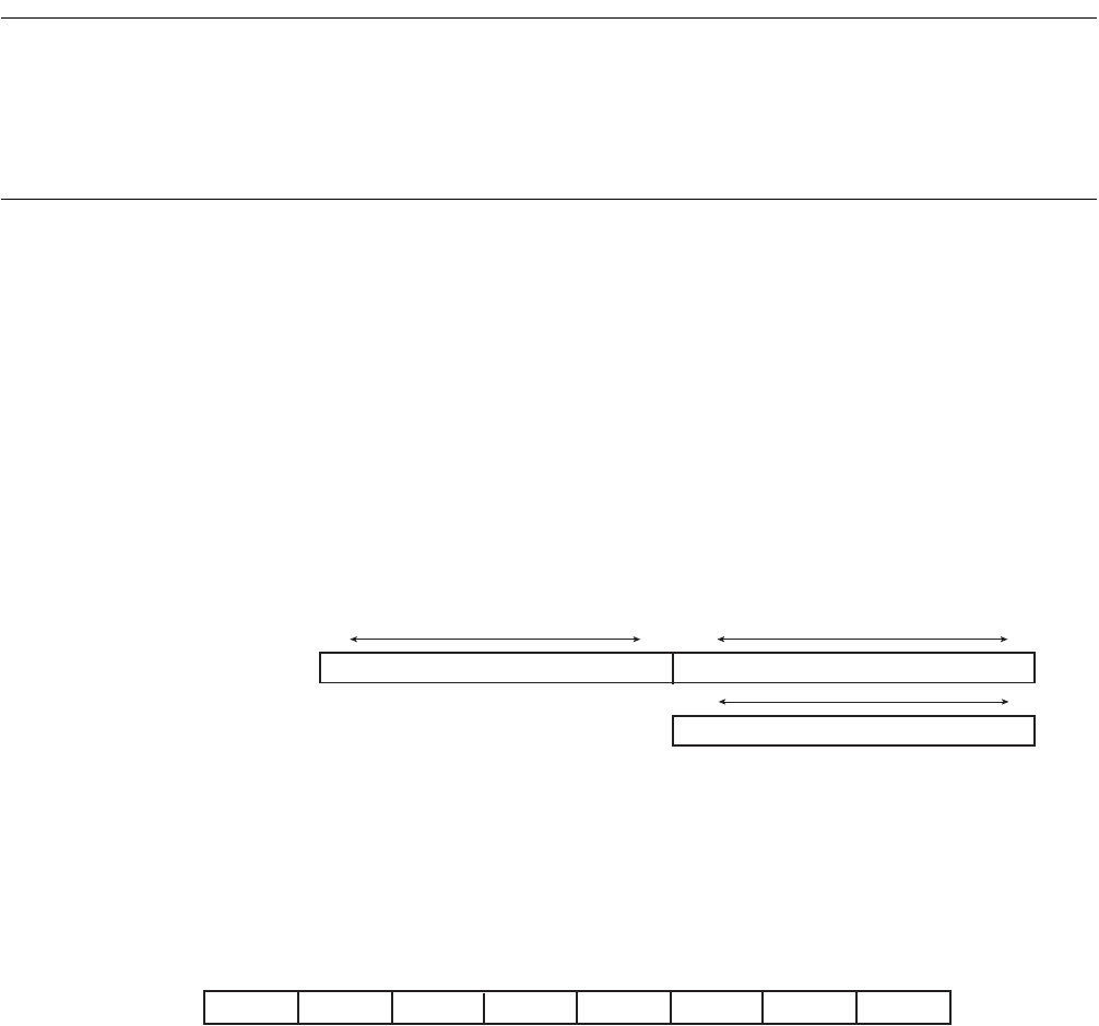
Figure 21.5-1 Hardware sequence flag
*: Word reading is disabled. (Only to be used under FR-CPU programming mode.)
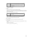
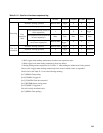
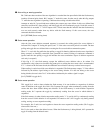
The hardware sequence flag can be acquired as data by reading any address (odd addresses in the case of
byte access) of the flash memory while executing auto algorithm. There are 5 valid bits of data, each of
them expresses the auto algorithm status.
Figure 21.5-2 Hardware sequence flag (At Half word, Byte access)
These flags are meaningless in FR-CPU ROM mode. Half-word or byte reading must be carried out under
FR-CPU programming mode only.
7 0 bit 15 8
(Indeterminate) Hardware sequence flag
Hardware sequence flag
7 0
bit
At read Halfword
At read Byte (Only odd number address)
7 6 5 4 3 2 1 0 bit
DPOLL TOGGLE TLOVER
Indeterminate
SETIMR TOGGL2
Indeterminate Indeterminate


