


WN-5230-S VideoWall User’s Guide
13
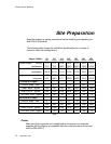
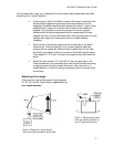
To allow proper cooling, the minimum required clearance to the rear of the
Unit is 4 inches.
If installed in a video wall configuration, a minimum of 12 inches to the ceiling
from the top of the highest display is needed if the units are installed from the
front.
Cables and Signals
Video connections from the signal source to the display depend on the type
of signal supplied by the source. The compatible data inputs are: PC
800x600 (SVGA), PC 640x480 (VGA), MAC 800X600 or 640X480, 31.5 kHz
and 15.75 kHz (progressive scan) RGBS video, composite video, and
S-video.
The Loop-Thru video output uses a standard 15 pin VGA type connector for
output to an external computer monitor or to another WN-5230-S. The format
of the Loop-Thru video is same as the source video.
The video cables used should be high quality and shielded to insure the best
image quality when displayed. VGA and MAC will have RGB with separate H-
Sync and V-Sync. RGBS video will come out RGBS with the composite sync
on the connector’s H-Sync pin. RGB Sync on Green sources will loop-thru
RGBS-Sync on Green. Displays with the VIM-300 option also have
Composite Video and S-Video loop-thru connectors.
Using poor quality cables can lead to picture noise, jitter and crosstalk.
Even good quality cables that are longer than 10 feet may produce
noise and jitter in the image if the source signals are not amplified.
Control data enters the display via the RS-232 In connection, and is supplied
to an adjacent display (if used) via the RS-232 Out connector. High quality
shielded cables designed for RS-232 communication should be used to
ensure proper data transmission and control. The wiring of the RS-232
cables must be straight through (pin 1 to pin 1, pin 2 to pin 2, etc…) and not
wired for “null modem”.