WN-5230-S VideoWall User’s Guide
87
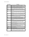
Rear Panel Controls
Control Description
MONITOR ID
16-position rotary switches select a unique Monitor ID number
for each unit in a video wall configuration. The two switches
have a total number of 256 individual Monitor ID settings.
GROUP - ID numbers are 0 – 9 and A – F for a total of 16
different settings. Each number is equal to that
number times 16. A setting of 3 is equal to 48.
UNIT - ID numbers are 0 – 9 and A – F for a total of 16
different settings. Each number is equal to that
number times one. A setting of 3 equals 3, a setting
of B equals 11.
The Monitor ID number is the combination of the Group ID plus
the Unit ID. A Group ID number of 2 and a Unit ID number of 5
equals a Monitor ID of 37.
This setting also delays the time between an “on” command to
the VideoWall and the ignition of the lamp. The delay is
approximately 2 seconds times the Monitor Unit ID number.
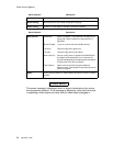
POWER
Power On/STBY push-button switch. Controls power to the lamp
and fans by toggling unit between ON and STBY
modes.
Power On/Off
Rocker switch near the A/C power input connector. Main AC
power switch.
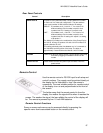
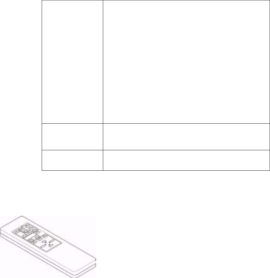
Remote-Control
Use the remote control or RS-232 input for all setup and
control functions. The remote must be pointed directly at
the display for the VideoWall to “see” the remote’s
commands. The most reliable position for remote control
of the display is on an axis perpendicular to the front of
the screen.
The farther away that the remote control is from the
display, the weaker the signal will be when it reaches the
screen. The weaker the signal, the less reliable the control of the display will
be. The remote is powered by two 1.5 volt AAA batteries.
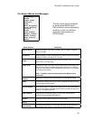
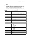
Remote Control Functions
Some on-screen sub-menus can be accessed directly by pressing the
specific menu item’s associated button on the remote control.


