


Clarity Visual Systems
September 1999
26
displays on it. (If the BAS-520 is used with Ultra-
Thin Mullion screens, remove the adapter plate
before you put the unit on the base.) Stack the
next higher row. Sliding the legs of each display
into the mating sockets of the display in the first
(lower) row.
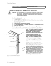
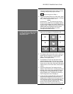
C. Insert a bolt (supplied). Insert a bolt through the
hole in side wall of the lower unit and into each
leg of the unit above. Tighten a nut on this bolt to
lock the units together. See Figure 1 above.
Tighten all the bolts after you have checked for
straightness, as in Step A above.
D. Continue with higher rows of displays. Lock each
display to the adjacent displays after the row
above it (if any) has been installed. Check for
straightness on each row.
E. For added stability, use the tapped holes in the
rear of the legs of the upper units to fasten to a
solid support, such as a structural wall. The
threaded inserts in each leg are female 5/16-18
UNC.
F. Check that all displays in the video wall are
locked together. And straight.
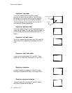
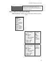
3. Start with the display unit in the
center of the bottom row. This
will be the Base Unit. Align the
Base Unit’s adapter plate. (If the
bottom row has an even number of
display units, choose either middle
one. This step can be done before
the wall is built, if necessary.)
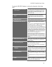
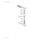
A. Look at the sides of the Adapter Frame. (See
Figure 3, below.) Starting at the top edge and
moving down you will see a large Locking Screw,
a pointed Alignment Bolt, and an Alignment Hole.
Near the middle of each side is a threaded hole
for the Alignment Tool’s spring-loaded screws.
(Do not attach the Alignment Tool yet.) At the
bottom of the side notice the Alignment Hole, the
Alignment Bolt, and the Locking Screw.
B. Look at all the Alignment Bolts of all units. They
should all be the same distance out. The factory
ships the display with a “shipping shim” behind
this bolt. If you have to adjust these bolts, you
should remove this shim. Save it. Use it later, if
you need to ship the units. When you ship Ultra-
Thin Mullion screen displays, always have the
Alignment Bolt either tighten onto the shipping
shim, or tighten down completely.
C. Check to see that the Adapter Frame of the Base
Unit is centered on the chassis. If the frame is not
centered on the chassis opening, for instance, if it
is offset to the left, then all the other frames will
have to be offset in this same direction. It is best if
this first frame is nicely centered on its chassis
opening.
D. Check to see that all the Locking Screws are
tight.
E. Measure the opening diagonally, from corner to
corner in both directions, and compare the
results. Be sure to measure from exactly the
same points each time. An accuracy of 1/32
nd
inch (0.8 mm) is necessary for most applications,
but the more accurately you can do this,
particularly in the bottom center unit, the better
the video wall will be ali
g
ned and the better the