3
1. 1 : 1 Connection 3-3
Serial Communications
RS-422/485 Connection
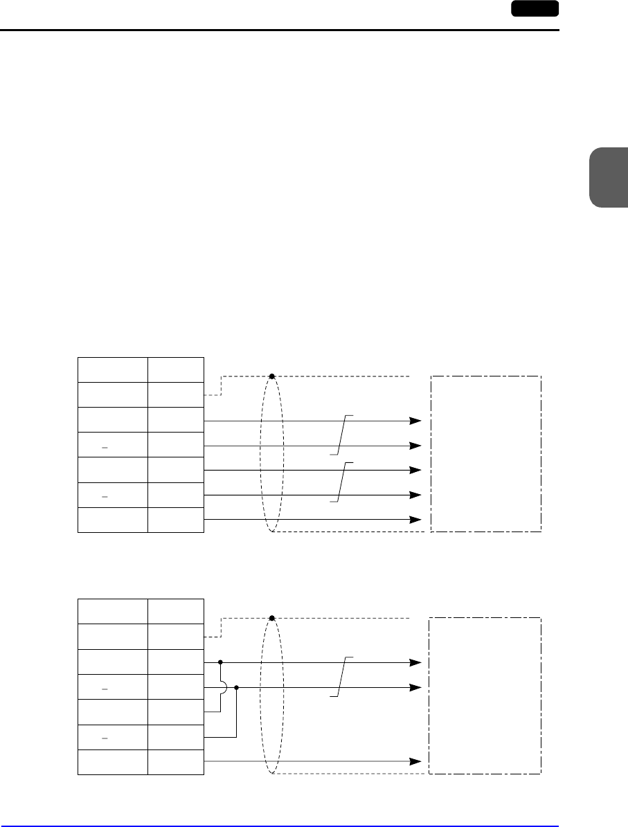
• Connect twist-pair cables between +SD/−SD and +RD/−RD.
• If the PLC has the terminal for signal ground (SG), be sure to connect a wire.
• Connect the shielded cable either to the V7 series or PLC side. This connection
diagram shows the case where the shielded cable is connected on the V7 series side.
When connecting the shielded cable to the V7 series side, connect it to pin 1 of the
connector or the connector case cover.
• To use a terminal block for connection, use Hakko Electronics’ “TC485” optionally
available.
• For the terminating resistance on the V7 series, turn the DIP switch (DIPSW7) to the
ON position on the side towards the rear.
• Twist-pair cables of 0.3 mm sq. or above are recommended.
4-wire system:
2-wire system:
V-SFT Setting
For serial communications, the following settings on the V-SFT editor are required. The
settings in the [Select PLC Type] and [Comm. Parameter] dialogs are shown on the Main
Menu screen of the V7 series. (Refer to “Chapter 2 MONITOUCH Operations.”)
FG
+RD
RD
+SD
SD
1
24
25
12
13
SG 7
V7 (CN1)
Signal Name Pin No.
Shield
To the PLC’s
RS422 port
Receive data (+)
Send data (+)
SG
Receive data (−)
Send data (−)
FG
+RD
RD
+SD
SD
1
24
25
12
13
SG 7
V7 (CN1)
Signal Name Pin No.
Shield
To the PLC’s
RS422 port
Send/receive data (+)
SG
Send/receive data (−)


