


3-28 6. V-Link
-Type
-Address
Specify the memory address to be accessed.
- Expansion code
Set the slot number of the SPU memory of the MITSUBISHI PLC or the CPU
number of the YOKOGAWA PLC.
Example:
MITSUBISHI Slot No. 0: 00H
MITSUBISHI Slot No. 1: 01H
YOKOGAWA CPU No. 1: 00H
YOKOGAWA CPU No. 2: 01H
- Port number
1 : 1, Multi-link............................................ Not used
Multi-drop................................................... PLC port number
Temperature controller............................... Temperature controller port number
- File No.
Specify the file number set in the [Memory Card Setting] dialog of the V-SFT editor.
- Record No.
Specify the record number set in the [Memory Card Setting] dialog of the V-SFT
editor.
- System reserved
Enter “0” (= 30 in the ASCII code) for the number of bytes. The number of bytes for
“system reserved” varies depending on the model.
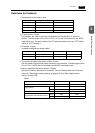
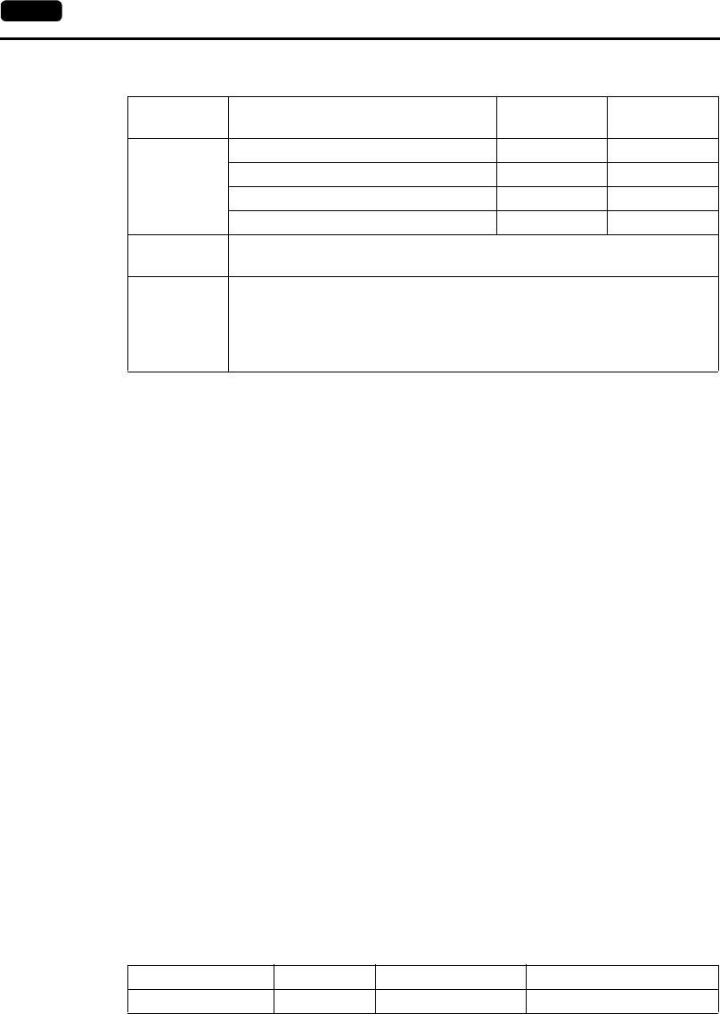
Example:
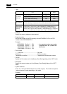
Type
Code
(Hexadecimal)
ASCII
V7 internal
memory
$u (user memory) 00H 3030
$s (system memory) 01H 3031
$L (non-volatile word memory) 02H 3032
$LD (non-volatile double-word memory) 03H 3033
PLC memory
Depends on the PLC to be used. Set the type number indicated for
“Available Memory” of respective PLCs on the Hardware Specifications.
Temperature
control/PLC2
memory
Depends on the PLC to be connected to the temperature controller and
PLC2 function. Set the type number indicated for “Available Memory” of
respective temperature controllers on the Temperature Control Network
Manual. Set the type number indicated for “Available Memory” of respective
PLCs on the Hardware Specifications when using the PLC2Way function.
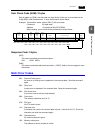
Model No. of Bytes Code (Hexadecimal) ASCII
V7 internal memory 10 0000000000H 30303030303030303030
* If no expansion code or port number
is required, enter “00” (= 3030 in the
ASCII code).