


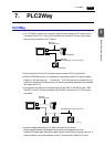
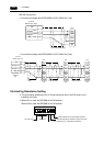

3-34 7. PLC2Way
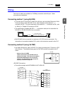
<RS-485 Connection>
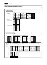
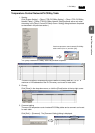
• Connection example with MITSUBISHI A1SJ71UC24-R4 (1 set)
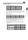
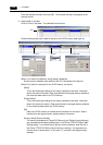
• Connection example with MITSUBISHI A1SJ71UC24-R4 (3 set)
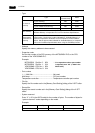
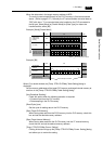
Terminating Resistance Setting
• The terminating resistance of the V7 series should be set on the DIP switch in the
backside of the unit.
• When MJ1 is used: Set DIPSW6 to the ON position.
When MJ2 is used: Set DIPSW8 to the ON position.
PLC
FG
SG
+SD/RD
SD/RD
5
1
2
SDA
SDB
SG
RDB
RDA
* Use the shielded cable.
V7 series
Modular jack, 8-pin
(Black)
(Green)
(Red)
PLC
FG
SG
+SD/RD
SD/RD
5
1
2
SDA
FG
SDB
SG
RDB
RDA
PLC
SDA
FG
SDB
SG
RDB
RDA
PLC
SDA
FG
SDB
SG
RDB
RDA
* Use the shielded
cable.
V7 series
Modular jack, 8-pin
(Black)
(Green)
(Red)
Terminating
resistance
(ON)
* Use shielded
twist-pair cables.
Terminating
resistance
(OFF)
* Use shielded
twist-pair cables.
Terminating
resistance
(ON)
Terminating
resistance
(ON)
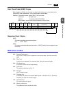
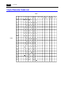
ON
12345678
CF auto load
MJ2 (modular jack 2) terminating resistance
Not used
CN1 RD terminating resistance at pins 24 and 25
MJ1 (modular jack 1) terminating resistance