


3
1. 1 : 1 Connection 3-7
Serial Communications
• SCRN_No. (n + 2) Screen number command
Use example: To specify a screen number from the PLC:
When “D0” is set for [Read Area], the screen number is written in “D2” of the
PLC.
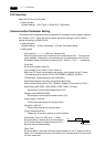
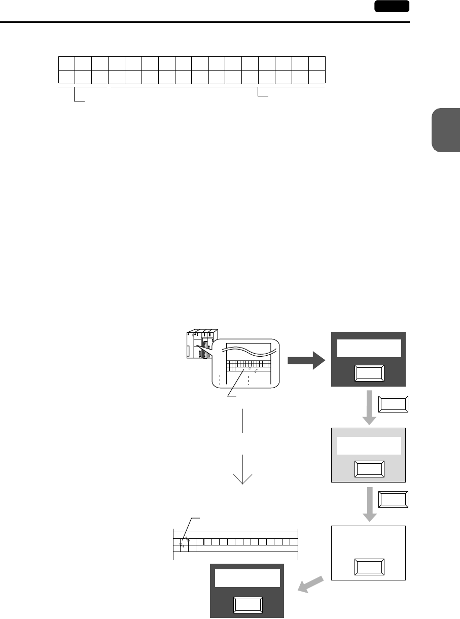
Problem example: The screen display does not change when a screen number is
specified from the PLC.
If the same number as the one specified for “n + 2” is already contained in this
memory address, the screen display does not change even if it is specified
again. For example, if screen No. 5 is specified from the PLC and it was once
changed to screen No. 2 → No. 0 by internal switches, normally it cannot be
returned to the former screen No. 5 that was specified by an external command,
because the external screen command number (5) remains the same as before
in the memory address (“D2” in the read area) for the screen number
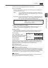
command.In such a case, it is possible to forcibly switch the screen to the
screen number contained in “D2” in the read area at the leading edge [0 → 1] of
bit 14 of the memory address for the screen status command (“D1” in the read
area).
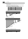
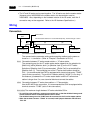
Screen number
15 14 13 12 11 10 09 08 07 06 05 04 03 02 01 00
000
System reserved (setting [0])
run
D001
D002
D000
5
No. 5
No. 2
No. 2
No. 0
No. 0
No. 3
No. 2
No. 0
15 14 13 12 11 10 09 08 07 06 05 04 03 02 01 00
0 1 0 0 0 0 0 0 0 0 0 0 0 0 0 0
0 0 0
5
D000
D001
D002
No. 5
No. 2
Screen forced switching (bit 14)
Read area “n + 2”
= Screen number command
Data in the read area “n+ 2” remains the same even
if the actual screen has been switched internally.
To show screen No. 5 again using an external screen
command, set [0→1] to bit 14 of read area “n + 1.”
Screen No. 5
Screen No. 2
Screen No. 0
Screen No. 5