


1-18 6. Names and Functions of Components
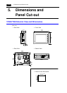
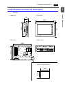
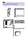
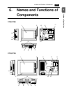
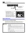
V712/V712i
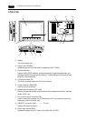
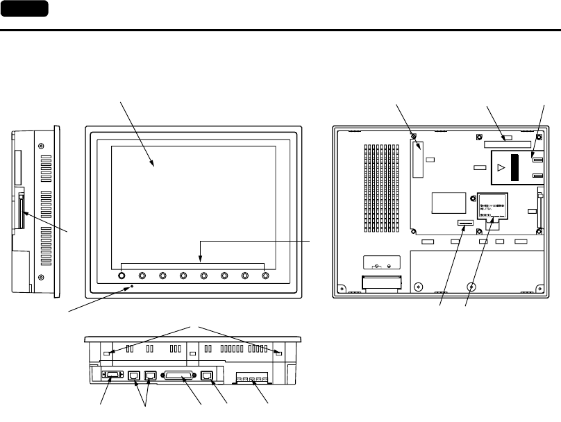
1. Display
This is the display unit.
2. Power Lamp (POWER)
Illuminates (green) when the power is supplied to the V7 series.
3. Function switches
Used for RUN /STOP selection, contrast adjustment, brightness adjustment and
backlight ON/OFF (according to the setting). These switches can be used as user
switches in the RUN mode.
4. CF card connector (CF)
This is the connector where the CF card is inserted.
5. Printer connector (PRINTER)
Used for printer connection.
6. Modular jack connectors (MJ1, MJ2)
Used for screen data transfer and connection with temperature controller, barcode
reader, CREC, etc.
7. PLC communication connector (CN1)
Used for connection between the V7 series and a PLC or an external control unit
(computer, custom controller, etc).
8. 10BASE-T connector (LAN) ................ V7i only
Used for Ethernet connection.
9. Power input terminal block
Supplies the power to the V7 series (100 to 240 VAC, 24 VDC)
SYSTEM
F1 F2 F3
F4
F5 F6 F7
POWER
CN5
MEMORY
CN6
CF
PRINTERMJ2MJ1
CN1
LAN
100-240VAC
L N
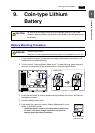
See operating or maintenance
instruction for type of battery
to be used.
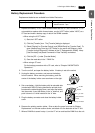
Battery replacement.
2
1
3
4
56 789
10
11 12 13
14 15