


3
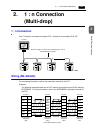
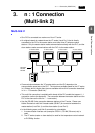
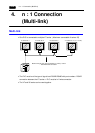
3. n : 1 Connection (Multi-link 2) 3-13
Serial Communications
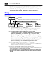
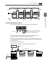
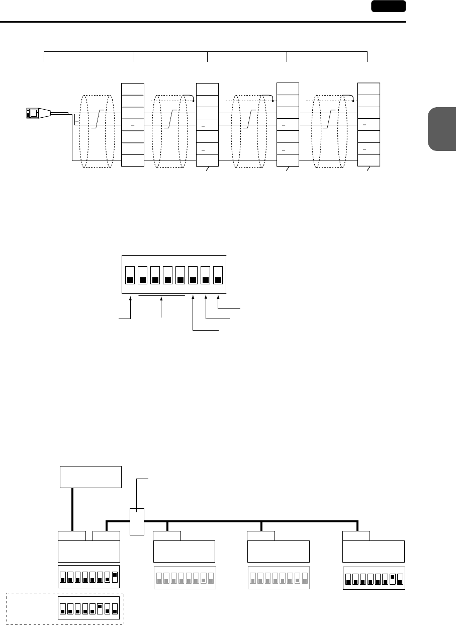
Terminating Resistance Setting
• The terminating resistance of the V7 series should be set on the DIP switch.
• When the PLC and the master station are connected via RS-422/485, set the
terminating resistance at the PLC and the master station (CN1).
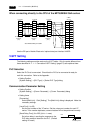
• When the V7 series (master and slave stations) are connected via RS-485 (2-wire), set
the terminating resistance at the V7 series master station (MJ1/2) and the terminating
slave station (CN1).
Terminating Resistance Setting Example
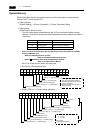
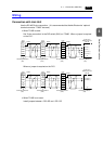
1. When the PLC is connected to V7 series master station via RS-232C:
(b) (c) (d) (e)
FG
+SD
SD
+RD
RD
SG
SG
SG
+
+
FG
+SD
SD
+RD
RD
SG
FG
+SD
SD
+RD
RD
SG
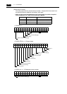
Signal
Name
To be installed by the user
Terminal block
V7 slave station
CN1+TC485
V7 slave station
CN1+TC485
V7 slave station
CN1+TC485
V7 master
station MJ1/2
Terminating
resistance
(OFF)
Terminating
resistance
(OFF)
Terminating
resistance
(OFF)
Terminating
resistance
(ON)
Signal
Name
Signal
Name
Signal
Name
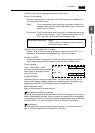
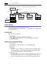
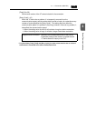
ON
12345678
CF auto load
MJ2 (modular jack 2) terminating resistance
Not used
CN1 RD terminating resistance at pins 24 and 25
MJ1 (modular jack 1) terminating resistance
RS-232C
ON
12345678
ON
12345678
ON
12345678
ON
12345678
ON
12345678
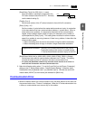
PLC
CN1CN1CN1CN1 MJ1/2
RS-485 (2-wire)
V7 master station
(= Local Port 1)
V7 slave station
(= Local Port 2)
V7 slave station
(= Local Port 3)
V7 slave station
(= Local Port 4)
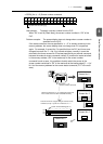
Terminal block
When MJ1 is
used:
When MJ2 is
used: