


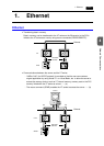
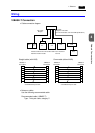
4-4 1. Ethernet
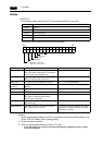
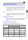
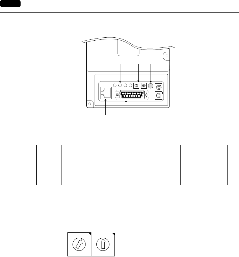
Nomenclature and Functions of Ethernet I/F Unit CU-03
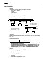
1. LED
Indicates the status of the communication.
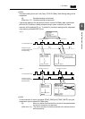
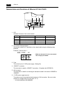
2. Port number setting switches
Set the port number of V7 specified on the network table using the following rotary
switches.
Example: To set port No. 1:
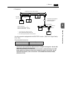
3. Fuse
This is the fuse for 12 VDC power supply. (Rating 2A)
4. 10BASE-T connector
This connector is used for 10BASE-T connection. (Compliant with IEEE802.3)
5. AUI connector
This connector is used for connecting the transceiver cable in the case of 10BASE2 or
10BASE5.
6. 12 VDC power supply terminal
The power source is required for the transceiver of AUI connection. Be sure to take
account of a voltage drop at CU-03 (max. 0.7 V).
* It is not necessary to use 10BASE-T.
Name Contents On Off
RX Data receive status Currently receiving Not receiving
TX Data send status Currently sending Not sending
LNK Link status (for 10BASE-T only) Normal Error
Cl Collision Data collision Normal
AUI +12V
10B-T RX TX LNK CI
ADR - LOW - HI FUSE 0V
123
45
6
0
1
2
3
4
5
6
7
8
9
A
B
C
D
E
F
0
1
2
3
4
5
6
7
8
9
A
B
C
D
E
F
ADR - LOW - HI
* Make sure that each I/F unit on the network
has a unique port number.