


5
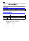
13. TOSHIBA PLC 5-87
Connection to PLCs
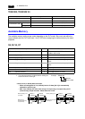
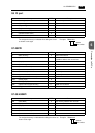
Available Memory
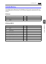
The available memory setting range varies depending on the PLC model. Be sure to set within the
range available with the PLC to be used. Use [TYPE] when assigning the indirect memory for macro
programs.
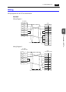
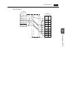
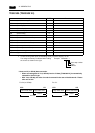
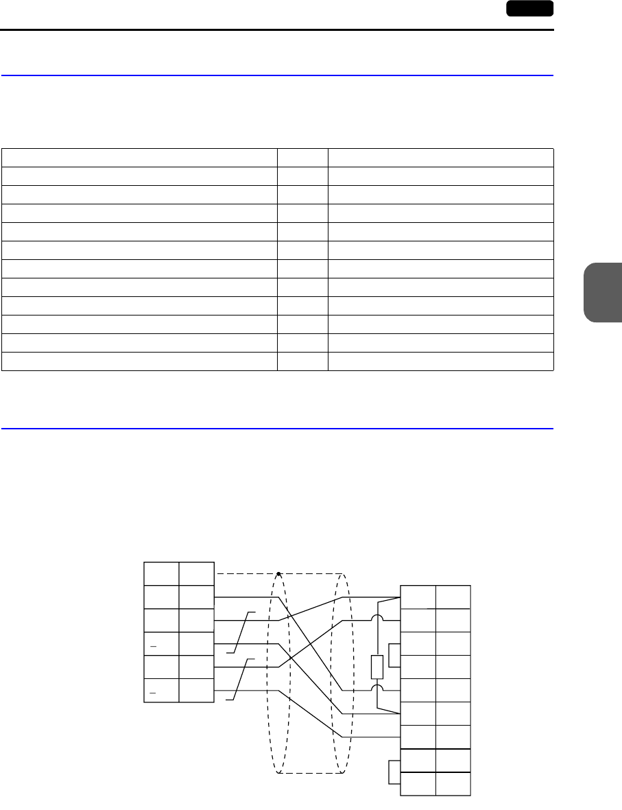
Wiring
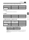
Wiring diagrams with the PLC are shown below.
RS-422
Wiring Diagram 1
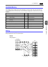
Memory TYPE Remarks
D (data register) 0
X (input register) 1 XW as word device
Y (output register) 2 YW as word device
R (auxiliary relay) 5 RW as word device
L (link relay) 6 LW as word device
W (link register) 7
F (file register) 8
TN (timer/current value) 9 Read only
CN (counter/current value) 10 Read only
TS (timer/contact) 11 Read only
CS (counter/contact) 12 Read only
V7 (CN1)
D-sub 25pin(Male: )
FG
SG
+SD
SD
+RD
2
PLC
D-sub 15pin(Male: )
3
4
RXA
TXA
CTSA
RTSA
5
RD SG7
7
1
12
13
24
25
10
11
12
13
RXB
TXB
CTSB
RTSB
*
R
* R: 120 Ω 1/2 W
* Use shielded twist-pair cables.
D-sub 25-pin (male)
D-sub 15-pin (male)