1
15. Printer Connection (PRINTER) 1-37
Hardware Specifications
15. Printer Connection
(PRINTER)
When the V7 series is connected to a printer, a screen hard copy, data sheet or sampling
data can be printed. To connect a printer with parallel interface, insert the cable into the
printer connector (PRINTER); to connect a printer with serial interface, insert the cable into
a modular jack (MJ1/MJ2).
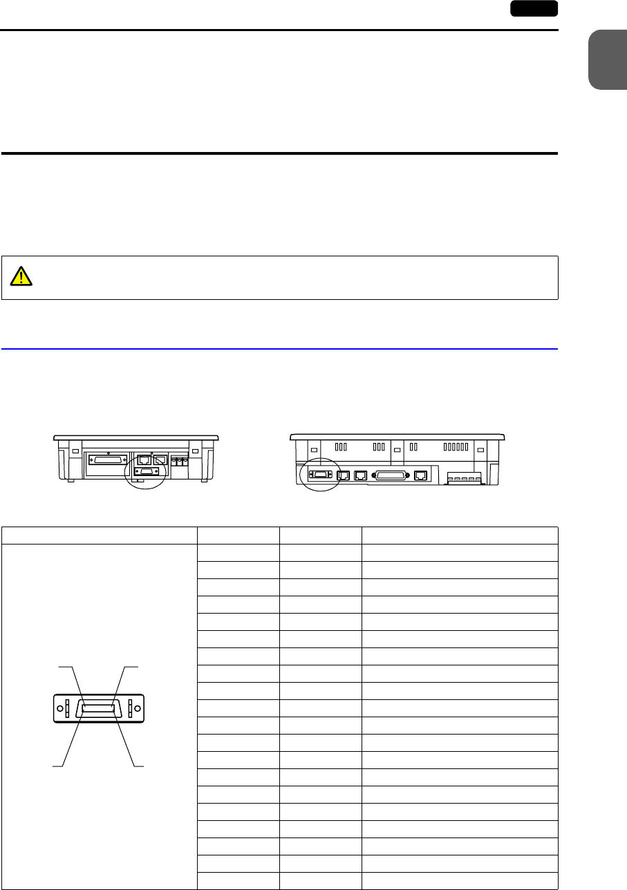
Printer Connector (PRINTER)
• This is the printer connector for parallel interface.
- For V708/V708i: - For V710/V710i/V712/V712i:
• The printer interface pins correspond to signals as given below.
CAUTION
Be sure to turn the printer off when the V7 unit is turned off.
Bottom View Bottom View
PRINTER (half-pitch 20-pin) Pin No. Signal Name Contents
1 STB# Strobe
2 PD0 Data 0
3 PD1 Data 1
4 PD2 Data 2
5 PD3 Data 3
6 PD4 Data 4
7 PD5 Data 5
8 PD6 Data 6
9 PD7 Data 7
10 GND
11 BUSY# Busy
12 GND
13 SELECT
14 INTP# INP PROME#
15 PFAT# FAULT#
16 GND
17 GND
18 P+5V PRN+5
19 GND
20 GND
11 20
110


