


1
6. Names and Functions of Components 1-19
Hardware Specifications
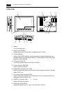
10. Mounting holes
Used for inserting fixtures when securing the V7 series to the mounting panel.
11. Communication interface unit connector (CN5)
This is the connector where the communication unit (CU-xx, optional) for OPCN-1,
T-LINK, CC-Link, Ethernet, FL-net (OPCN-2), PROFIBUS-DP or MELSECNET/10 is
mounted.
12.Option unit connector (CN6).....................V7i only
This is the connector where the option unit (EU-xx) for video, sound, RGB IN or RGB
OUT is mounted.
13.Add-on memory connector (MEMORY)
This is the connector where the optional FLASH memory cassette (V7EM-F) or SRAM
cassette (V7EM-S) is mounted.
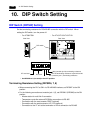
14. DIP switch
8-bit DIP switch used for setting terminating resistance of the CN1 signal line and the
MJ1/MJ2 RS-422/485 signal line.
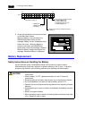
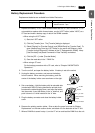
15.Battery holder
Contains a backup battery for SRAM and clock. When the battery voltage drops,
replace the battery with a new one (V7-BT).