


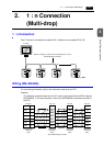

3-2 1. 1 : 1 Connection
Wiring
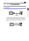
Prepare the communication cable with the PLC on your side. Refer to the following
information for the cable. For more information on the connection to respective PLCs, refer
to “Chapter 5 Connection to PLCs.”
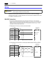
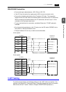
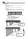
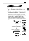
RS-232C Connection
• Connect the shielded cable either to the V7 series or PLC side. This connection
diagram shows the case where the shielded cable is connected on the V7 series side.
When connecting the shielded cable to the V7 series side, connect it to pin 1 of the
connector or the connector case cover.
• Twisted pairs of 0.3 mm sq. or above are recommended.
• If noise disturbs communications, use twist-pair cables between SD/SG and RD/SG.
DANGER
Electric shock hazard
Shut the power off before connecting cables.
FG
SD
RD
RS
CS
1
2
3
4
5
SG 7
V7 CN1
Signal Name Pin No.
Shield
To the PLC’s
RS232C port
Receive data
SG
Send data
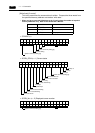
FG
SD
RD
RS
CS
1
2
3
4
5
SG 7
V7 CN1
Signal Name Pin No.
Shield
To the PLC’s
RS232C port
Receive data
Send data
SG
SG