


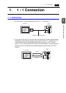
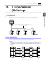
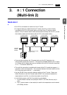
3-6 1. 1 : 1 Connection
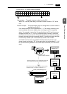
System Memory
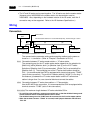
[Read Area]/[Write Area] of the system memory must be secured for communications
between the V7 series and the PLC.
• Setting Position
[System Setting] → [Comm. Parameter] → [Comm. Parameter] dialog
• Setting Items
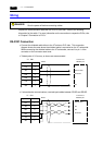
[Read Area] (3 words or more)*
- This is the area where commands from the PLC are received for screen display
changes. Consecutive three words from the specified memory address are used as
“read area.”
* When you have created screens with the following function,the number of required
memory addresses vary.
• When the sampling function is used:
Refer to the Reference Manual (Function).
•When [
Read/Write Area GD-80 Compatible] is checked:
Refer to the GD-80 User’s Manual.
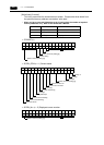
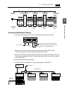
- Set “0” for all the bits not used in the read area.
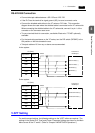
• RCVDAT (n) Sub command/data
• SCRN_COM (n + 1) Screen status command
Address Name Contents
n RCVDAT Sub command/data
n + 2 SCRN_COM Screen status command
n + 1 SCRN_No Screen number command
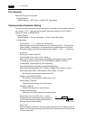
BZ0 ([0 → 1] leading edge)
Free
To forcibly change the bits for “free”
area, the same data is written to
CFMDATA in [Write Area] after the
screen is displayed.
Use this function for watch dog or
display scanning.
BZ1 [0 → 1] leading edge)
System reserved (setting [0])
Calendar setting ([0 → 1] leading edge)
System reserved (setting [0])
15 14 13 12 11 10 09 08 07 06 05 04 03 02 01 00
0000 0 00000000
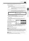
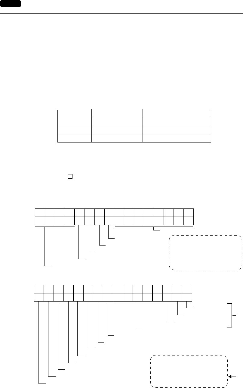
Overlap 0
Normal overlap or call-overlap:
0 → 1: ON
1 → 0: OFF
Multi-overlap:
Level (with exceptions)
15 14 13 12 11 10 09 08 07 06 05 04 03 02 01 00
00000
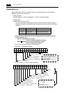
Overlap 1
Overlap 2
System reserved (setting [0])
Global macro execution ([0 → 1] leading edge)
Data Sheet output ([0 → 1] leading edge)
Screen hard copy ([0 → 1] leading edge)
Backlight (level)
Analog RGB input (level)
Screen internal switching (level)
Screen forced switching ([0 → 1] leading edge)
Data read refresh ([0 → 1] leading edge)