


1-20 7. Mounting Procedure
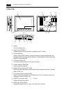
7. Mounting Procedure
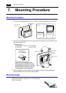
Mounting Procedure
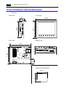
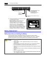
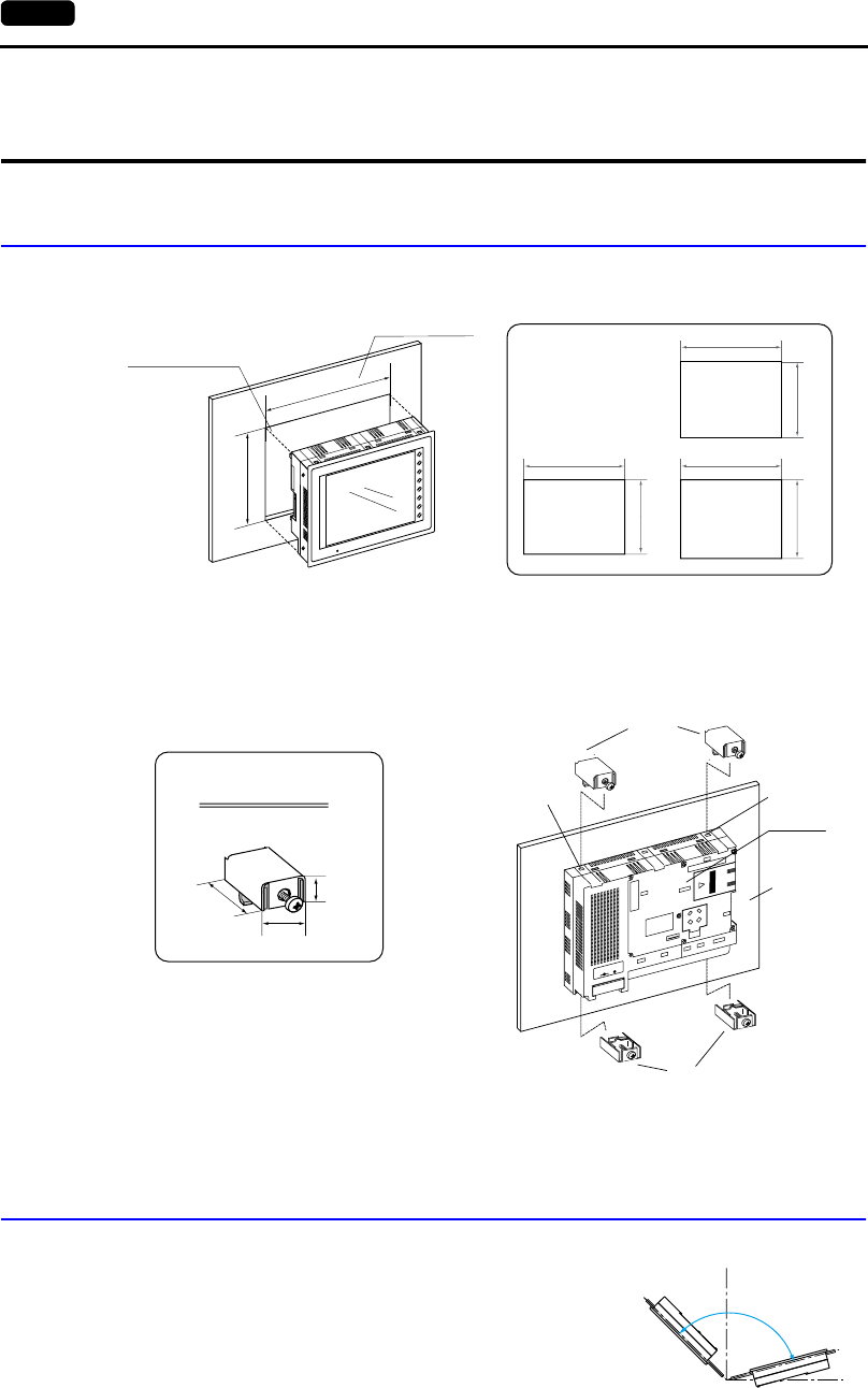
1. Cut out the mounting panel (max. thick: 5 mm) to match the dimensions shown below.
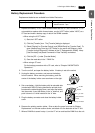
2. Insert four fixtures attached to the V7 series into the mounting holes, and tighten them
with the locking screws.
Tightening torque
V708/V708i/V710/V710i: 0.3 to 0.5 N•m
V712/V712i: 0.5 to 0.7 N•m
* When the V7 unit is attached to the
mounting panel, the fixtures and frame
grounds (FG) are connected. To prevent
static electricity, be sure to connect the
mounting panel to the frame ground.
3. Mount the gasket in contact with the mounting panel so that it will be sandwiched
securely between the unit and the mounting plate.
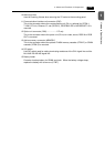
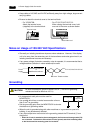
Mounting Angle
Install the unit within the angle of 15° to 135° degrees as
shown on the right.
165.5
220.5
+0.5
−0
−0
+
0.5
246.2
313
V712/V712i
V708/V708i
216.2
289
+0.5
−0
−0
+
0.5
V710/V710i
+0.5
−0
−0
+
0.5
F1
F
2
F3
F
4
F5
F
6
F7
SY
S
T
E
M
PO
W
E
R
216.2
2
8
9
+
0
.
5
−
0
−
0
0.5
Mounting panel
Panel cut-out hole
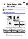
• Panel cut-out dimensions
(Unit: mm)
M
J
1
M
J
2P
R
I
N
T
E
R
C
F
C
N
5
M
E
M
O
R
Y
C
N
6
L
A
NC
N
1
1
0
0
-
2
4
0
V
A
C
L
N
Fixtures
Mounting hole
Mounting hole
V7 series
Mounting panel
Fixtures
17.8
10.5
30.0
Fixture dimensions
(Unit: mm)
15°
135°
90°
0°
D
i
s
p
l
a
y
D
i
s
p
l
a
y