


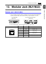

1-32 12. Modular Jack (MJ1/MJ2)
Transferring Screen Data
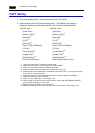
• Use modular jack 1 (MJ1) when transferring screen data.
• When [Editor Port] is selected for [Modular Jack 1] on the V-SFT editor, it is possible to
transfer data in the RUN mode because the RUN/STOP mode (on the Main Menu
screen) can be automatically selected. Also RUN/STOP mode is automatically
selected for on-line editing and simulation.
• When an option other than [Editor Port] is selected for [Modular Jack 1], select the
STOP mode (on the Main Menu screen) and transfer screen data. Simulation or on-line
editing is not available.
• When transferring screen data, use Hakko Electronics’ data transfer cable (V6-CP) 3 m
to connect the V7 series to a personal computer.
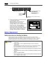
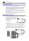
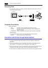
Barcode Reader Connection
• It is possible to receive the signal from a barcode reader by connecting the barcode
reader at the modular jack (MJ1/2) of the V7 series.
• To connect a barcode reader to the modular
jack (MJ1/2), use Hakko Electronics’ optional
cable (V6-BCD).
Length: 3 m
with modular plug
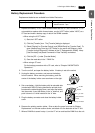
• Notes on Connection
- In the case of barcode readers with CTS and RTS control, it may be necessary to
install a jumper to RTS and CTS. Otherwise the barcode reader may not work
correctly.
- The external power supply (+5 V) is max. 150 mA. (Refer to page 1-29.)
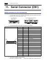
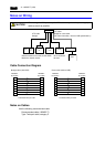
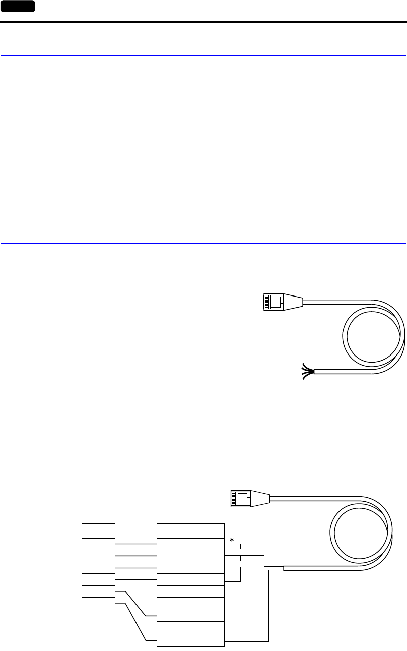
• When using the barcode reader that was connected to V4 (MONITOUCH’s old version),
connect it to the D-sub 9-pin female connector using the V6-BCD cable as shown
below.
12345678
Brown: +5V
Red: 0V
Orange: RXD
Yellow: TXD
Pin No
1
2
3
4
5
6
7
8
9
CTS
RXD
TXD
RTS
SG
+5V
12345678
RTS
TXD
RXD
CTS
SG
+5V
Signal
Name
Orange:RXD
Signal
Name
* Install a jumper between
CTS and RTS.
Yellow: TXD
Red: 0 V
Brown: +5 V
D-sub 9-pin (female)Barcode reader