


Installation
Document 800-00919 Rev F 27
02/08
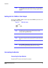
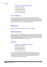
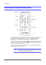
Figure 2-8 Alarm Input Connector Strips
AI 1 to 4 (Alarm In)
You can use external devices to signal the DVR to react to events. Mechanical or
electrical switches can be wired to the AI (Alarm In) and GND (Ground) connectors. The
threshold voltage for NC (Normally Closed) is above 4.3V and should be stable at least
0.5 seconds to be detected. The threshold voltage for NO (Normally Open) is below
0.3V. See Chapter 3, Configuration for configuring alarm input.
GND (Ground)
Connect the ground side of the Alarm input to the GND connector.
ARI (Alarm Reset In)
An external signal to the Alarm Reset In can be used to reset both the Alarm Out signal
and the internal buzzer of the DVR. Mechanical or electrical switches can be wired to
the ARI (Alarm Reset In) and GND (Ground) connectors. The threshold voltage is below
0.3V and should be stable at least 0.5 seconds to be detected. Connect the wires to the
ARI (Alarm Reset In) and GND (Ground) connectors.
Alarm Out
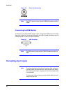
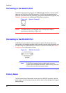
Figure 2-9 Alarm Output Connector Strips
The DVR can activate external devices such as buzzers or lights. Mechanical or
electrical switches can be wired to the NC (Normally Closed) and C (Common)
connectors or NO (Normally Open) and C (Common) connectors. The amount of
current permitted is up to 0.5 A for 125 VAC, 1 A for 30 VDC. See Chapter 3,
Configuration for configuring alarm output.