


107
Explanation Section
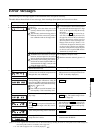
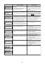
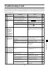
Error Messages
The following error messages appear if the instrument does not operate correctly.
The table below shows kinds of error message, their meanings (description) and corrective actions.
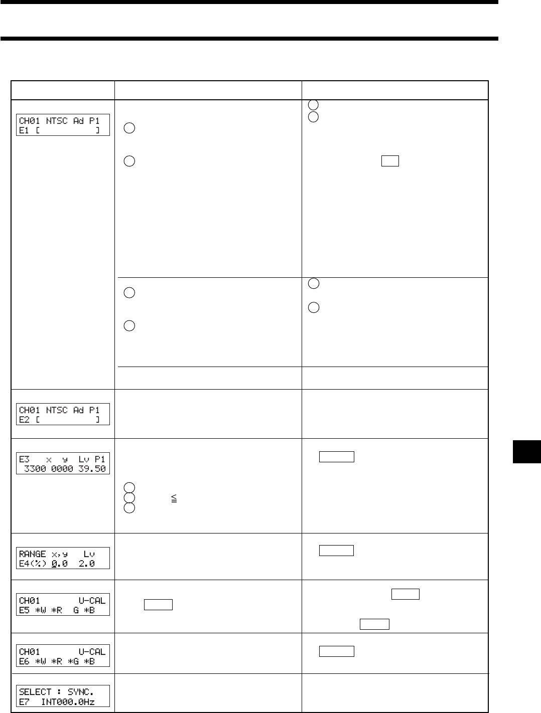
(Note) • *1: If “E1” appears, the cause of the error can be located easily by checking the serial no. of the probe used to make settings and
the current probe serial no. For details, refer to page 104.
• *2: “E2” will not appear if “E1” is currently displayed.
E1
E2
E3
E4
E5
E6
E7
Error Message Cause: (Description) Corrective Action
1 Perform user calibration or set the target color.
2 Use the same probe as the one used to perform
user calibration and set the target color. (Page
26) Or set the target color using the currently
used probe.
(If you press the MR key for two to four sec-
onds while a menu is displayed on the LCD,
the upper line will show the user calibration/
emission characteristic, and the lower line
shows the probe no. used to set the target color.
However, in the case of xyLv, T∆uvLv, u’v’Lv
or XYZ mode, the upper line shows the probe
no. that was used to perform user calibration.
In the case of analyzer mode, it shows the probe
no. that was used to input the RGB emission
characteristic for analyzer mode.
• When xyLv or T∆uvLv measurement mode
is selected
1 No target color has been set to the
memory channel since shipment from
factory.
2 The currently used measuring probe is
different from the one used to perform
user calibration and set the target color.
•
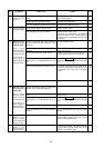
When analyzer measurement mode (RGB) is selected
1
The RGB emission characteristic for analyzer
mode has not been input for the selected
memory channel since shipment from factory.
2
The currently used measuring probe is differ-
ent from the one used to input the RGB emis-
sion characteristic for display’s analyzer mode
and set the target color (W).
1 Input the RGB emission characteristic
for display’s analyzer mode.
2 Perform corrective action 2 given in *3
*4
• The settings made to the selected memory
channel have been lost.
• Make them again.
• An error has occurred due to shift of the zero
point because the ambient temperature has
changed since zero calibration.
• Perform zero calibration. (Page 34)
(Measurement can still be performed even
if “E2” is currently displayed.)
•
An attempt was made to set an incorrect value
when performing user calibration or setting the
target color to CH00 by entering its values directly.
Incorrect calibration values mean the following.
1
One of x, y and Lv is “0”.
2
1 – x – y 0
3
Values which are beyond the instrument’s calcu-
lation capability or other contradicting values
• Enter correct values and then press the
ENTER key.
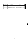
• “0%” was set when setting the analog dis-
play range.
• No entry has been made for one of W, R, G
and B.
• The White key was pressed when the mea-
suring range for target color (W) was ex-
ceeded.
• Enter a correct value and then press the
ENTER key. The settable range is from
0.1 to 99%. (Page 68)
•
Enter values for the color for which no values have been
made, and then press the ENTER key. (Page 53 or 58)
•
Enter values for the color for which no Input the target
color values (W) that are within the measuring range,
and press the ENTER key.
*1
*2
*2
• Enter correct values and then press the
ENTER key.
• An attempt was made to set an incorrect
value when performing matrix calibration.
• Set the correct value, the correct value is
value between 40-200 Hz.
• Although INT SYNC mode is selected, the
setup value isn
’
t correct.