


20
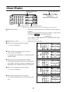
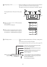
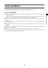
3 Analog display section ............................ Displays the difference (%) between the measured value and the tar-
get color or the difference (%) between measured values.
The range for each dot can be set between 0.1 and 99%. (Page 68)
The range has been set to 10% prior to factory ship-
ment.
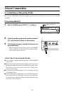
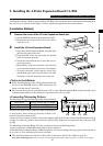
● When xylv, T∆uvLv, u'v'Lv or XYZ measurement
mode is selected
∆x, ∆y and ∆Lv are displayed.
● When an analyzer measurement mode is selected
For G-reference R/G, B/G and ∆G are displayed.
For R-reference ∆R, B/R and G/R are displayed.
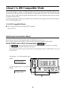
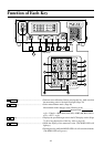
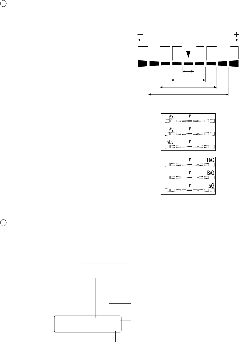
4 LCD display section ................................ Displays the memory channel, probe no., ID name, warning and set-
tings.
In case of error, an error message will appear.
(For a description of what to do in case of error, refer to page 107.)
+n×8% or
higher
Red Green Red
-
n×8%
or lower
Below ±n%
Below ±n×2%
Below ±n×4%
Below ±n×8%
CH00 EXT Ad P1H
[MINOLTA ]
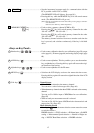
Displays the currently selected SYNC mode. (NTSC,
PAL, EXT, UNIV, INT) (Page 38)
Displays the currently selected measurement speed.
(A.F.S) (Page 36)
Displays the calibration mode for the currently se-
lected memory channel. (d.a.m) (Page 56)
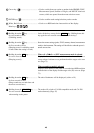
Probe no. (Page 43)
H will be displayed for High Luminance Measuring
Probe(CA-PH02/05). For Measuring Probe(CA-P02/
05) nothing will be displayed.
ID name display area (Page 66)
Memory channel
(Page 48)